Mitsubishi Lancer Evolution IX. Manual — part 458

TROUBLESHOOTING
MULTIPORT FUEL INJECTION (MPI)
13A-307
STEP 9. Perform voltage measurement at C-119
engine-ECU connector.
• Disconnect connector, and measure at harness
side.
• Voltage between terminal No. 60 and earth.
OK: System voltage
Q: Is the check result normal?
YES :
Go to Step 10 .
NO :
• Check intermediate connector A-13
*1
or
C-31
*2
and repair if necessary. If
intermediate connector is normal, check
and repair harness between C-119
(terminal No. 60) engine-ECU connector
and battery.
• Check power supply line for short
circuit.
STEP 10. Connector check: C-119 engine-ECU
connector
Q: Is the check result normal?
YES :
Go to Step 11 .
NO :
Repair or replace the connector.
AK501994
65
43
50
42
49
41
48
60
61
64
46
47
58
59
67
68
45
56
66
52 51
44
53
62
54
63
57
55
AB
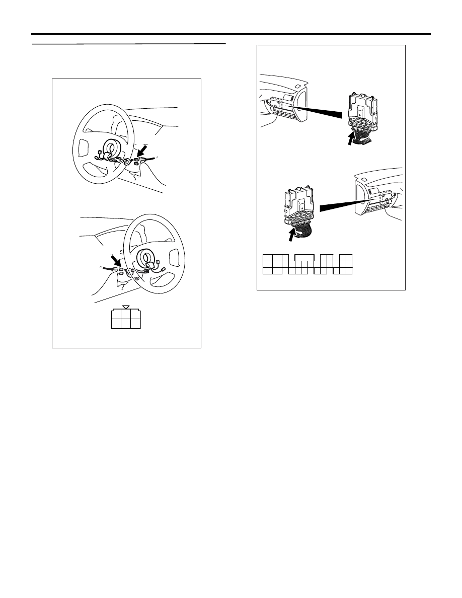
Connector: C-119
C-119 (GR)
C-119 (GR)
Harness side connector
<L. H. drive vehicles>
<R. H. drive vehicles>
AK501994
65
43
50
42
49
41
48
60
61
64
46
47
58
59
67
68
45
56
66
52 51
44
53
62
54
63
57
55
AB
Connector: C-119
C-119 (GR)
C-119 (GR)
Harness side connector
<L. H. drive vehicles>
<R. H. drive vehicles>

TROUBLESHOOTING
MULTIPORT FUEL INJECTION (MPI)
13A-308
STEP 11. Perform resistance measurement at
C-119 engine-ECU connector.
• Disconnect connector, and measure at harness
side.
• Resistance between terminal No. 46 and earth,
and No. 58 and earth.
OK: 2
Ω or less
Q: Is the check result normal?
YES :
Go to Step 12 .
NO :
Check and repair harness between C-119
(terminal No. 46 and No. 58) engine-ECU
connector and body earth.
• Check earthing line for open circuit
and damage.
STEP 12. Connector check: C-119 engine-ECU
connector
Q: Is the check result normal?
YES :
Go to Step 13 .
NO :
Repair or replace the connector.
AK501994
65
43
50
42
49
41
48
60
61
64
46
47
58
59
67
68
45
56
66
52 51
44
53
62
54
63
57
55
AB
Connector: C-119
C-119 (GR)
C-119 (GR)
Harness side connector
<L. H. drive vehicles>
<R. H. drive vehicles>
AK501994
65
43
50
42
49
41
48
60
61
64
46
47
58
59
67
68
45
56
66
52 51
44
53
62
54
63
57
55
AB
Connector: C-119
C-119 (GR)
C-119 (GR)
Harness side connector
<L. H. drive vehicles>
<R. H. drive vehicles>

TROUBLESHOOTING
MULTIPORT FUEL INJECTION (MPI)
13A-309
STEP 13. Perform voltage measurement at C-119
engine-ECU connector.
• Disconnect connector, and measure at harness
side.
• Voltage between terminal No. 57 and earth.
OK: System voltage
Q: Is the check result normal?
YES :
Go to Step 14 .
NO :
Check and repair harness between B-12X
(terminal No. 3) engine control relay
connector and C-119 (terminal No. 57)
engine-ECU connector.
• Check earthing line for open/short
circuit.
STEP 14. Perform voltage measurement at C-119
engine-ECU connector.
• Disconnect connector, and measure at harness
side.
• Using jumper wire, connect C-119 (terminal No.
57) engine-ECU connector and earth.
• Voltage between terminal No. 47 and earth, and
No. 59 and earth.
OK: System voltage
Q: Is the check result normal?
YES :
Go to Step 15 .
NO :
Check intermediate connector C-105 and
repair if necessary. If intermediate
connector is normal, check and repair
harness between C-119 (terminal No. 47
and No. 59) engine-ECU connector and
B-12X (terminal No. 4) engine control relay
connector.
AK501994
65
43
50
42
49
41
48
60
61
64
46
47
58
59
67
68
45
56
66
52 51
44
53
62
54
63
57
55
AB
Connector: C-119
C-119 (GR)
C-119 (GR)
Harness side connector
<L. H. drive vehicles>
<R. H. drive vehicles>
AK305003
2
1
3
4
AB
Connector : B-12X
B-12X
Harness side
connector
Relay box’s
triangle marks
AK501994
65
43
50
42
49
41
48
60
61
64
46
47
58
59
67
68
45
56
66
52 51
44
53
62
54
63
57
55
AB
Connector: C-119
C-119 (GR)
C-119 (GR)
Harness side connector
<L. H. drive vehicles>
<R. H. drive vehicles>
AK305003
2
1
3
4
AB
Connector : B-12X
B-12X
Harness side
connector
Relay box’s
triangle marks
TROUBLESHOOTING
MULTIPORT FUEL INJECTION (MPI)
13A-310
STEP 15. Check harness between C-208 (terminal
No. 2) ignition switch connector and C-117
(terminal No. 99) engine-ECU connector.
NOTE: Before checking harness, check intermediate
connectors C-123, C-210 and C-211, and repair if
necessary.
• Check power supply line for damage.
Q: Is the check result normal?
YES :
Go to Step 16 .
NO :
Repair the damaged harness wire.
AK305251
1
2
3
4
5
6
Harness side connector
Connector: C-208
C-208
<L. H. drive vehicles>
<R. H. drive vehicles>
C-208
AB
AK501996
80
87
81
94
85
82
84
93
86
98
99
74
92
73
83
88
91
95
97 96
100
89
78
71
90
76
77
75
72
79
AB
Connector: C-117
C-117 (GR)
C-117 (GR)
Harness side connector
<L. H. drive vehicles>
<R. H. drive vehicles>
Нет комментариевНе стесняйтесь поделиться с нами вашим ценным мнением.
Текст