Mitsubishi Lancer Evolution IX. Manual — part 457
TROUBLESHOOTING
MULTIPORT FUEL INJECTION (MPI)
13A-303
OPERATION
• The battery voltage is applied to the engine con-
trol relay (terminal No. 1 and No. 4).
• The engine-ECU (terminal No. 57) makes the
power transistor in the unit be in "ON" position
and makes currents go on the engine control
relay coil, and that makes the relay be in "ON"
position.
• When the engine control relay is in "ON" position,
the battery voltage is supplied to the
engine-ECU, the sensor and the actuator from
the engine control relay (terminal No. 4).
• The engine-ECU (terminal No. 46, No. 58) is
grounded to the vehicle body.
FUNCTION
• When the ignition switch ON signal is input to the
engine-ECU, the engine-ECU places the engine
control relay in the ON position. Accordingly, the
battery voltage is supplied to the engine-ECU,
sensor and actuator.
PROBABLE CAUSES
• Failed engine control relay
• Open/short circuit in engine control relay circuit or
loose connector contact
• Failed engine-ECU
DIAGNOSIS PROCEDURE
NOTE:
.
*1: L.H. drive vehicles
*2: R.H. drive vehicles
STEP 1. Check battery voltage.
• Measure battery voltage during cranking.
OK: 8 V or more
Q: Is the check result normal?
YES :
Go to Step 2 .
NO :
Check battery (Refer to GROUP 54A
−
Battery
− On-vehicle Service − Battery test
).
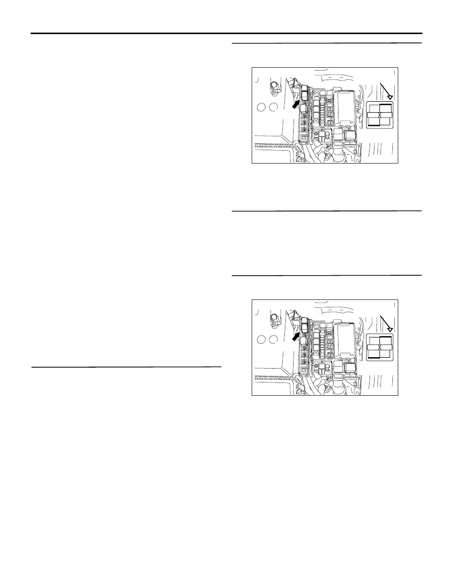
STEP 2. Connector check: B-12X engine control
relay connector
Q: Is the check result normal?
YES :
Go to Step 3 .
NO :
Repair or replace the connector.
STEP 3. Check engine control relay.
• Check engine control relay (Refer to
Q: Is the check result normal?
YES :
Go to Step 4 .
NO :
Replace the engine control relay.
STEP 4. Perform voltage measurement at B-12X
engine control relay connector.
• Remove relay, and measure at relay box side.
• Voltage between terminal No. 1 and earth, also
between terminal No. 2 and earth.
OK: System voltage
Q: Is the check result normal?
YES :
Go to Step 5 .
NO :
Check intermediate connector A-13
*1
or
C-31
*2
, and repair if necessary. If
intermediate connector is normal, check and
repair harness between B-12X (terminal No.
1, No. 2) engine control relay connector and
battery.
• Check power supply line for
open/short circuit.
AK305003
2
1
3
4
AB
Connector : B-12X
B-12X
Harness side
connector
Relay box’s
triangle marks
AK305003
2
1
3
4
AB
Connector : B-12X
B-12X
Harness side
connector
Relay box’s
triangle marks

TROUBLESHOOTING
MULTIPORT FUEL INJECTION (MPI)
13A-304
STEP 5. Connector check: C-117 engine-ECU
connector
Q: Is the check result normal?
YES :
Go to Step 6 .
NO :
Repair or replace the connector.
STEP 6. Perform voltage measurement at C-117
engine-ECU connector.
• Disconnect connector, and measure at harness
side.
• Ignition switch: "ON"
• Voltage between terminal No. 99 and earth.
OK: System voltage
Q: Is the check result normal?
YES :
Go to Step 9 .
NO :
Go to Step 7 .
AK501996
80
87
81
94
85
82
84
93
86
98
99
74
92
73
83
88
91
95
97 96
100
89
78
71
90
76
77
75
72
79
AB
Connector: C-117
C-117 (GR)
C-117 (GR)
Harness side connector
<L. H. drive vehicles>
<R. H. drive vehicles>
AK501996
80
87
81
94
85
82
84
93
86
98
99
74
92
73
83
88
91
95
97 96
100
89
78
71
90
76
77
75
72
79
AB
Connector: C-117
C-117 (GR)
C-117 (GR)
Harness side connector
<L. H. drive vehicles>
<R. H. drive vehicles>

TROUBLESHOOTING
MULTIPORT FUEL INJECTION (MPI)
13A-305
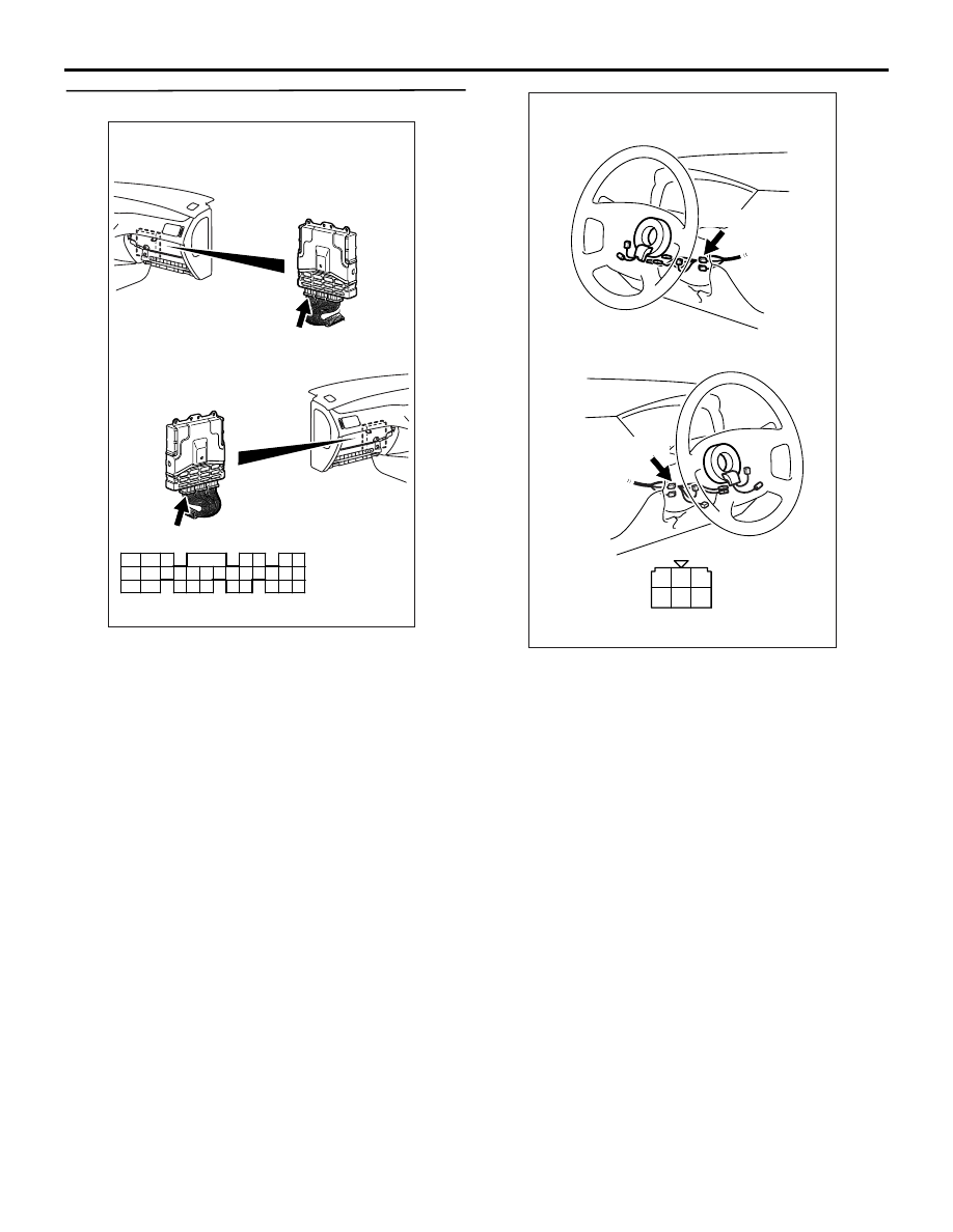
STEP 7. Connector check: C-208 ignition switch
connector
Q: Is the check result normal?
YES :
Go to Step 8 .
NO :
Repair or replace the connector.
AK305251
1
2
3
4
5
6
Harness side connector
Connector: C-208
C-208
<L. H. drive vehicles>
<R. H. drive vehicles>
C-208
AB
TROUBLESHOOTING
MULTIPORT FUEL INJECTION (MPI)
13A-306
STEP 8. Check ignition switch.
• Check ignition switch (Refer to GROUP 54A −
Ignition Switch
− Ignition Switch − Inspection
).
Q: Is the check result normal?
YES :
• Check intermediate connectors C-123,
C-210 and C-211, then repair if
necessary. If intermediate connectors
are normal, check and repair harness
between C-117(terminal No. 99)
engine-ECU connector and C-208
(terminal No. 2) ignition switch
connector.
• Check power supply line for
open/short circuit.
NO :
Replace the ignition switch.
AK501996
80
87
81
94
85
82
84
93
86
98
99
74
92
73
83
88
91
95
97 96
100
89
78
71
90
76
77
75
72
79
AB
Connector: C-117
C-117 (GR)
C-117 (GR)
Harness side connector
<L. H. drive vehicles>
<R. H. drive vehicles>
AK305251
1
2
3
4
5
6
Harness side connector
Connector: C-208
C-208
<L. H. drive vehicles>
<R. H. drive vehicles>
C-208
AB
Нет комментариевНе стесняйтесь поделиться с нами вашим ценным мнением.
Текст