Mitsubishi Lancer Evolution IX. Manual — part 255
INPUT SIGNAL PROCEDURES
SMART WIRING SYSTEM (SWS) USING SWS MONITOR
54C-279
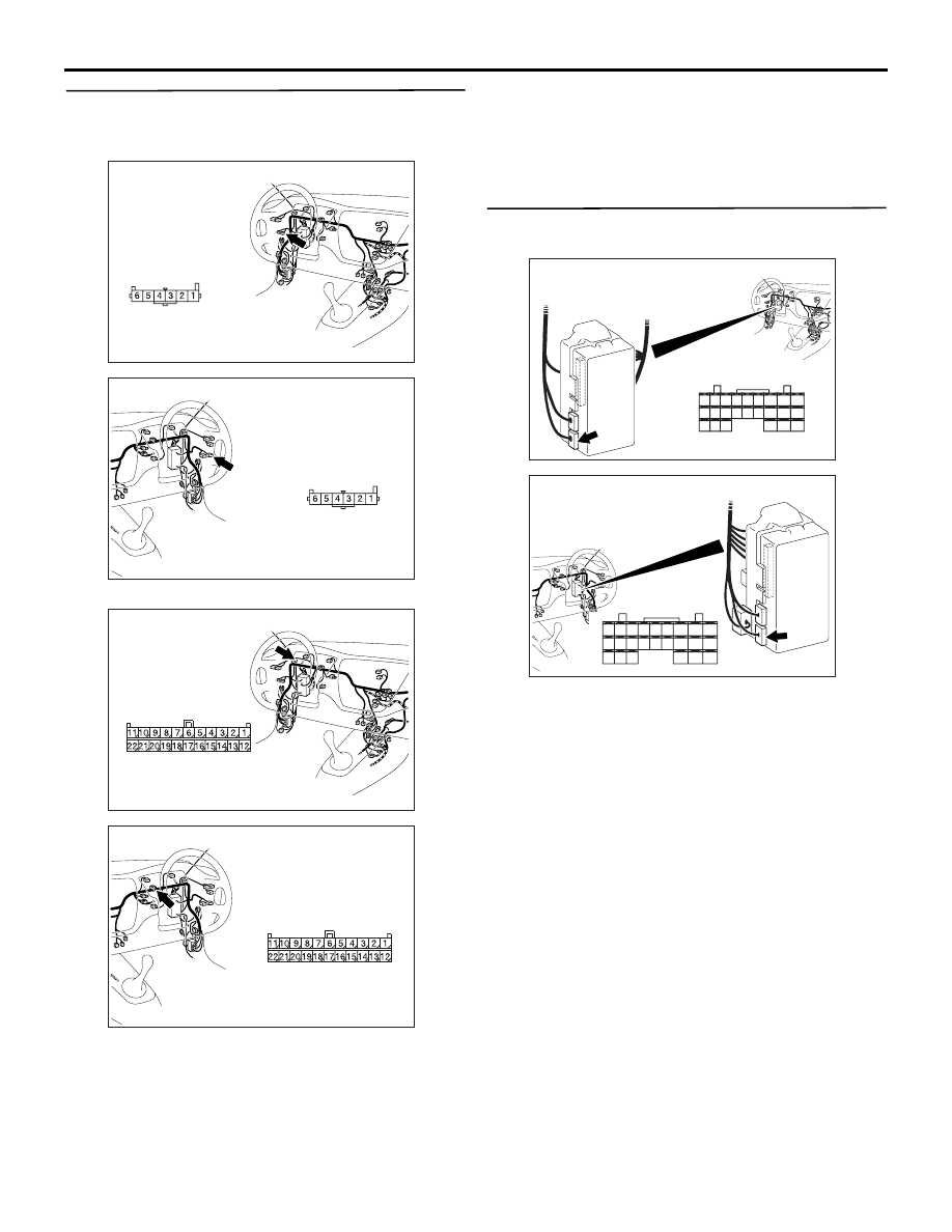
Step 4. Check the wiring harness between C-20
fog lamp switch connector terminal No.6 and
body earth.
NOTE:
Prior to the wiring harness inspection, check joint
connector C-101 <LH driver vehicles> or C-06 <RH
drive vehicles>, and repair if necessary.
• Check the earth wires for open circuit.
Q: Is the check result normal?
YES :
The trouble can be an intermittent
malfunction (Refer to GROUP 00
− How to
Cope with Intermittent Malfunction
NO :
Repair the wiring harness.
Step 5. Connector check: C-227 ETACS-ECU
connector
Q: Is the check result normal?
YES :
Go to Step 6.
NO :
Repair the defective connector.
AC310446
Harness side
AH
Connector: C-20
<LHD>
AC310456
Harness side
AI
Connector: C-20
<RHD>
AC310446
Connector: C-101
<LHD>
AF
Harness side
AC310456
Connector: C-06
<RHD>
AG
Harness side
AC310450
Connector: C-227
AG
Junction block
(rear view)
Harness side
<LHD>
28
37
43
29
44
38
23
32
41
24
25
26
27
34
42
36 35
33
21
22
30
39
40
31
AC310461
Harness side
Junction block (rear view)
Connector: C-227
AF
<RHD>
21
22
23
24
25
26
27
28
29
30
31
32
33
34
35
36
37
38
39
40
41
42
43
44
INPUT SIGNAL PROCEDURES
SMART WIRING SYSTEM (SWS) USING SWS MONITOR
54C-280
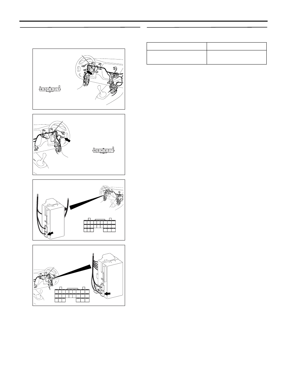
Step 6. Check the wiring harness between C-227
ETACS-ECU connector terminal No.21 and C-20
fog lamp switch connector terminal No.5.
• Check the input line for open circuit.
Q: Is the check result normal?
YES :
Go to Step 7.
NO :
Repair the wiring harness.
Step 7. Pulse check.
Check the input signal from the rear fog lamp switch.
OK: The M.U.T.-II/III sounds or the voltmeter
needle fluctuates.
Q: Is the check result normal?
YES :
The trouble can be an intermittent
malfunction (Refer to GROUP 00
− How to
Cope with Intermittent Malfunction
NO :
Replace the ETACS-ECU.
AC310446
Harness side
AH
Connector: C-20
<LHD>
AC310456
Harness side
AI
Connector: C-20
<RHD>
AC310450
Connector: C-227
AG
Junction block
(rear view)
Harness side
<LHD>
28
37
43
29
44
38
23
32
41
24
25
26
27
34
42
36 35
33
21
22
30
39
40
31
AC310461
Harness side
Junction block (rear view)
Connector: C-227
AF
<RHD>
21
22
23
24
25
26
27
28
29
30
31
32
33
34
35
36
37
38
39
40
41
42
43
44
System switch
Check condition
Rear fog lamp switch
When the switch is
turned from off to on
INPUT SIGNAL PROCEDURES
SMART WIRING SYSTEM (SWS) USING SWS MONITOR
54C-281
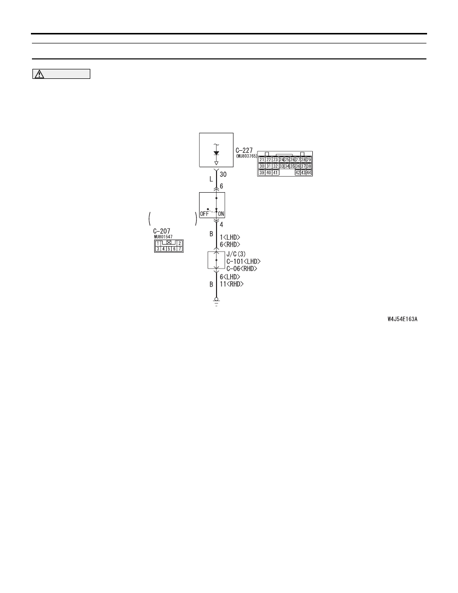
INSPECTION PROCEDURE L-9: The key reminder switch signal is not received.
CAUTION
Whenever the ECU is replaced, ensure that the
input signal circuit is normal.
COMMENTS ON TROUBLE SYMPTOM
Input signal from the key reminder switch is used to
operate the functions below. If the signal is abnormal,
these functions will not work normally.
• Key reminder function
• Keyless entry system
• Room lamps
POSSIBLE CAUSES
• Malfunction of the key reminder switch
• Malfunction of the ETACS-ECU
• Damaged harness wires and connectors
ETACS-
ECU
KEY
REMINDER
SWITCH
Wire colour code
B : Black LG : Light green G : Green L : Blue W : White Y : Yellow SB : Sky blue
BR : Brown O : Orange GR : Gray R : Red P : Pink V : Violet
WHEN KEY
IS REMOVED
Key Reminder Switch Input Circuit

INPUT SIGNAL PROCEDURES
SMART WIRING SYSTEM (SWS) USING SWS MONITOR
54C-282
DIAGNOSIS PROCEDURE
Step 1. Connector check: C-207 key reminder
switch connector
Q: Is the check result normal?
YES :
Go to Step 2.
NO :
Repair the defective connector.
Step 2. Check the key reminder switch.
Refer to GROUP 54A
− Ignition switch
.
Q: Is the check result normal?
YES :
Go to Step 3.
NO :
Replace the key reminder switch.
Step 3. Resistance measurement at the C-207 key
reminder switch connector
(1) Disconnect the connector, and measure at the
wiring harness side.
(2) Resistance between C-207 key reminder switch
connector terminal No.4 and body earth
OK: 2
Ω or less
Q: Is the check result normal?
YES :
Go to Step 5.
NO :
Go to Step 4.
AC310479
AC
Connector: C-207
<LHD>
Harness side
2
7 6
1
3
5 4
AC310481AC
Harness side
Connector: C-207
<RHD>
AC310479
AC
Connector: C-207
<LHD>
Harness side
2
7 6
1
3
5 4
AC310481AC
Harness side
Connector: C-207
<RHD>
AC301541
2
7 6
1
3
5 4
GY
Connector C-207
(Harness side)
Нет комментариевНе стесняйтесь поделиться с нами вашим ценным мнением.
Текст