Mitsubishi Lancer Evolution IX. Manual — part 253

INPUT SIGNAL PROCEDURES
SMART WIRING SYSTEM (SWS) USING SWS MONITOR
54C-271
DIAGNOSIS PROCEDURE
Step 1. Connector check: C-206 column switch
connector
Q: Is the check result normal?
YES :
Go to Step 2.
NO :
Repair the defective connector.
Step 2. Resistance measurement at the C-206
column switch connector
(1) Disconnect the connector, and measure at the
column switch side.
(2) Resistance between C-206 column switch
connector terminal No.6 and body earth
OK: The resistance should rise from 0 to
1 k
Ω when the windshield intermittent
wiper volume is rotated from "Fast" to
"Slow".
Q: Is the check result normal?
YES :
Go to Step 3.
NO :
Replace the column switch.
AC310479
AB
Connector: C-206
<LHD>
Harness side
AC310481AB
Harness side
Connector: C-206
<RHD>
AC310479
AB
Connector: C-206
<LHD>
Harness side
AC310481AB
Harness side
Connector: C-206
<RHD>
AC301541GV
Connector C-206
(Harness side)

INPUT SIGNAL PROCEDURES
SMART WIRING SYSTEM (SWS) USING SWS MONITOR
54C-272
Step 3. Connector check: C-228 ETACS-ECU
connector
Q: Is the check result normal?
YES :
Go to Step 4.
NO :
Repair the defective connector.
Step 4. Check the wiring harness between C-206
column switch connector terminal No.6 and
C-228 ETACS-ECU connector terminal No.66.
• Check the input line for open circuit.
Q: Is the check result normal?
YES :
Go to Step 5.
NO :
Repair the wiring harness.
AC310450
Connector: C-228
AE
Junction block (rear view)
Harness side
C-228(GR)
<LHD>
AC310461
Junction block (rear view)
Connector: C-228
AD
<RHD>
C-228(GR)
Harness side
AC310450
Connector: C-228
AE
Junction block (rear view)
Harness side
C-228(GR)
<LHD>
AC310461
Junction block (rear view)
Connector: C-228
AD
<RHD>
C-228(GR)
Harness side
AC310479
AB
Connector: C-206
<LHD>
Harness side
AC310481AB
Harness side
Connector: C-206
<RHD>

INPUT SIGNAL PROCEDURES
SMART WIRING SYSTEM (SWS) USING SWS MONITOR
54C-273
Step 5. SWS monitor data list.
<Selected item> ETACS ECU
• Ignition switch: ACC
• Wiper switch: INT
OK: The display will be changed as the inter-
mittent wiper volume is rotated.
Q: Is the check result normal?
YES :
The trouble can be an intermittent
malfunction (Refer to GROUP 00
− How to
Cope with Intermittent Malfunction
NO :
Replace the ETACS-ECU.
Item No.
Item name
Normal condition
Item 37
INT WIPE TIME
2.4 to 18.0 s
INPUT SIGNAL PROCEDURES
SMART WIRING SYSTEM (SWS) USING SWS MONITOR
54C-274
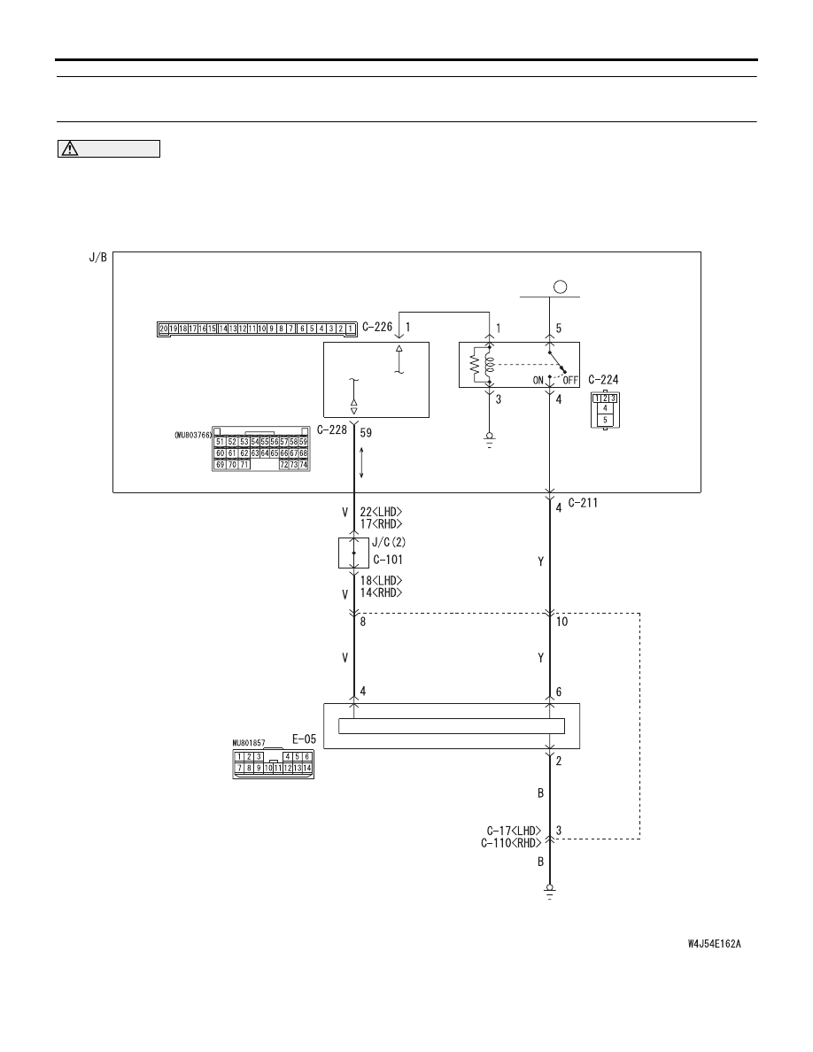
INSPECTION PROCEDURE L-7: When the power window main switch is operated, the switch signals
are not received.
CAUTION
Whenever the ECU is replaced, ensure that the
input signal circuit is normal.
J/B SIDE
POWER
WINDOW RELAY
ETACS-ECU
POWER WINDOW
MAIN SWITCH
CPU
Wire colour code
B : Black LG : Light green G : Green L : Blue W : White Y : Yellow SB : Sky blue
BR : Brown O : Orange GR : Gray R : Red P : Pink V : Violet
FUSIBLE
LINK
5
Power Window Main Switch Circuit
Нет комментариевНе стесняйтесь поделиться с нами вашим ценным мнением.
Текст