Mitsubishi Lancer Evolution IX. Manual — part 254
INPUT SIGNAL PROCEDURES
SMART WIRING SYSTEM (SWS) USING SWS MONITOR
54C-275
COMMENTS ON TROUBLE SYMPTOM
Input signal from the power window main switch is
used in order to check the power window main
switch and confirm how the system is communicating
with the ETACS-ECU. If the communication line is
defective, the power windows will not work normally.
POSSIBLE CAUSES
• Malfunction of the power window main switch
• Malfunction of the ETACS-ECU
• Damaged harness wires and connectors
DIAGNOSIS PROCEDURE
Step 1. Check the operation by using the power
window main switch.
Check if each window can be operated by means of
the power window main switch.
Q: Can each power window be operated by means of
the power window main switch?
YES :
Go to Step 2.
NO :
Refer to Inspection Procedure D-1 "Power
windows do not work at all
."
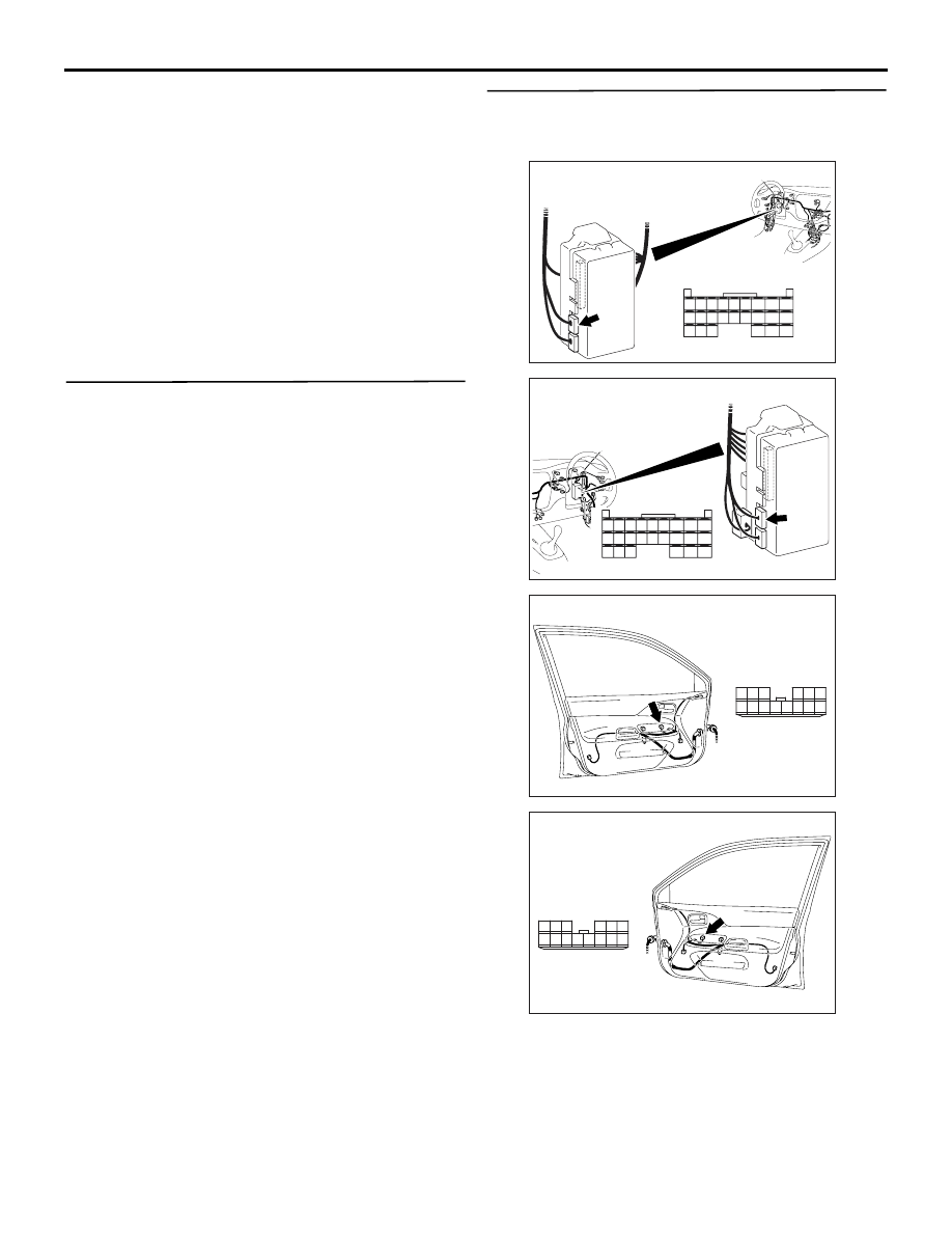
Step 2. Connector check: C-228 ETACS-ECU
connector and E-05 power window main switch
connector
Q: Is the check result normal?
YES :
Go to Step 3.
NO :
Repair the defective connector.
AC310450
Connector: C-228
AH
Junction block
(rear view)
Harness side
<LHD>
51
52
53
54
55
56
57
58
59
58 5756 55 54 53 52 51 60
74 7372
71 70 69
AC310461
Harness side
Junction block (rear view)
Connector: C-228
AG
<RHD>
51
52
53
54
55
56
57
58
59
58 5756 55 54 53 52 51 60
74 7372
71 70 69
AC310484
Harness side
AC
Connector: E-05 <LHD>
10
1
6
14
5
12
13
4
11
7
2
3
8
9
Front door (LH)
AC310493
AC
Connector: E-05
<RHD>
Harness side
10
1
6
14
5
12
13
4
11
7
2
3
8
9
Front door (RH)
INPUT SIGNAL PROCEDURES
SMART WIRING SYSTEM (SWS) USING SWS MONITOR
54C-276
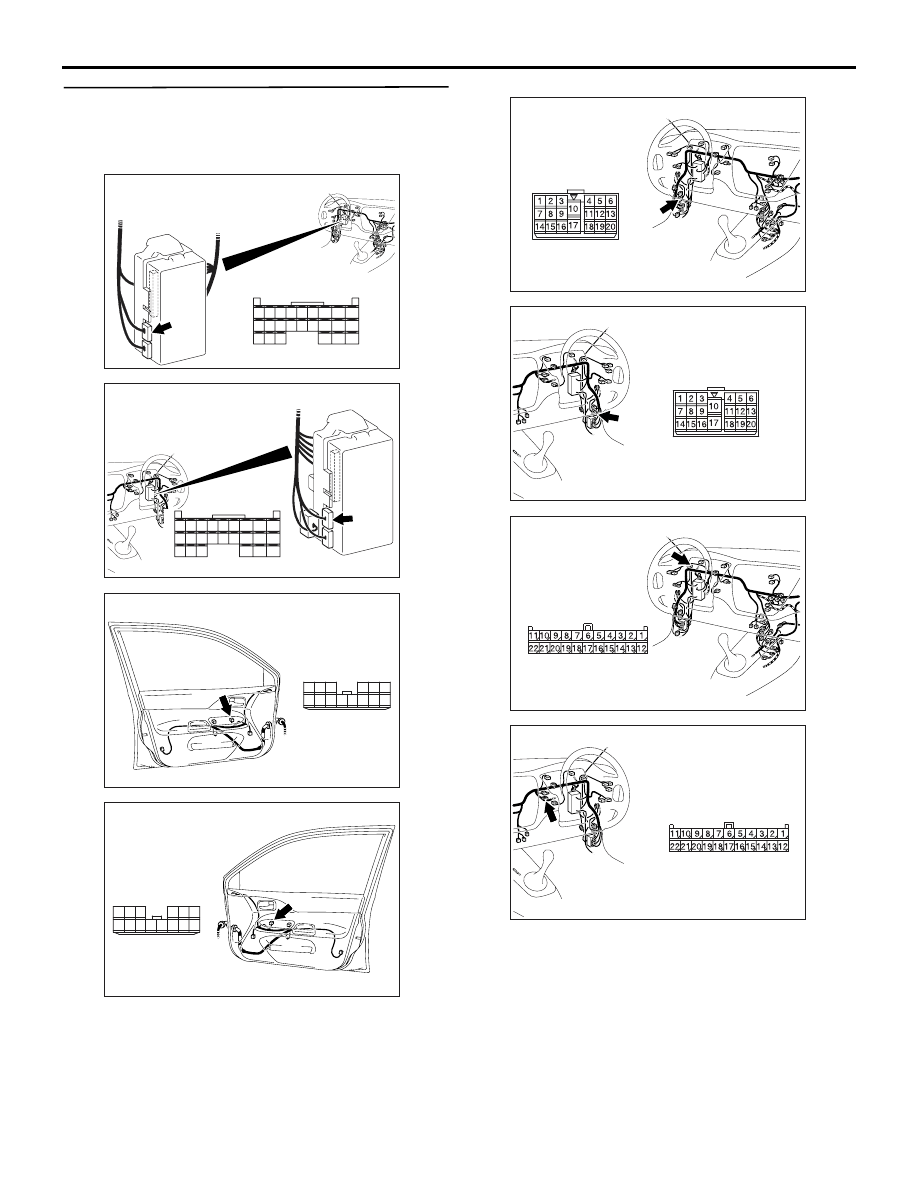
Step 3. Check the wiring harness between C-228
ETACS-ECU connector terminal No.59 and E-05
power window main switch connector terminal
No.4.
NOTE:
Prior to the wiring harness inspection, check interme-
diate connector C-17 <LH drive vehicles> or C-110
<RH drive vehicles> and joint connector C-101, and
repair if necessary.
• Check the communication lines for open circuit.
Q: Is the check result normal?
YES :
Go to Step 4.
NO :
Repair the wiring harness.
AC310450
Connector: C-228
AH
Junction block
(rear view)
Harness side
<LHD>
51
52
53
54
55
56
57
58
59
58 5756 55 54 53 52 51 60
74 7372
71 70 69
AC310461
Harness side
Junction block (rear view)
Connector: C-228
AG
<RHD>
51
52
53
54
55
56
57
58
59
58 5756 55 54 53 52 51 60
74 7372
71 70 69
AC310484
Harness side
AC
Connector: E-05 <LHD>
10
1
6
14
5
12
13
4
11
7
2
3
8
9
Front door (LH)
AC310493
AC
Connector: E-05
<RHD>
Harness side
10
1
6
14
5
12
13
4
11
7
2
3
8
9
Front door (RH)
AC310446
Connector: C-17
AC
<LHD>
AC310456
Connector: C-110
AE
<RHD>
AC310446
Connector: C-101
<LHD>
AF
Harness side
AC310456
Connector: C-101
<RHD>
AF
Harness side
INPUT SIGNAL PROCEDURES
SMART WIRING SYSTEM (SWS) USING SWS MONITOR
54C-277
Step 4. Replace the power window main switch,
and then retest the system.
Replace the power window main switch, and check
that the power window main switch signal is
received.
(1) Replace the power window main switch.
(2) Check that the power window main switch signal
is received.
Q: Is the check result normal?
YES :
The procedure is complete.
NO :
Replace the ETACS-ECU.
INSPECTION PROCEDURE L-8: The rear fog lamp switch signal is not received.
CAUTION
Whenever the ECU is replaced, ensure that the
input signal circuit is normal.
COMMENTS ON TROUBLE SYMPTOM
Input signal from the rear fog lamp switch is used to
operate the rear fog lamps. If the signal is abnormal,
the rear fog lamps will not illuminate and extinguish
normally.
POSSIBLE CAUSES
• Malfunction of the fog lamp switch
• Malfunction of the ETACS-ECU
• Damaged harness wires and connectors
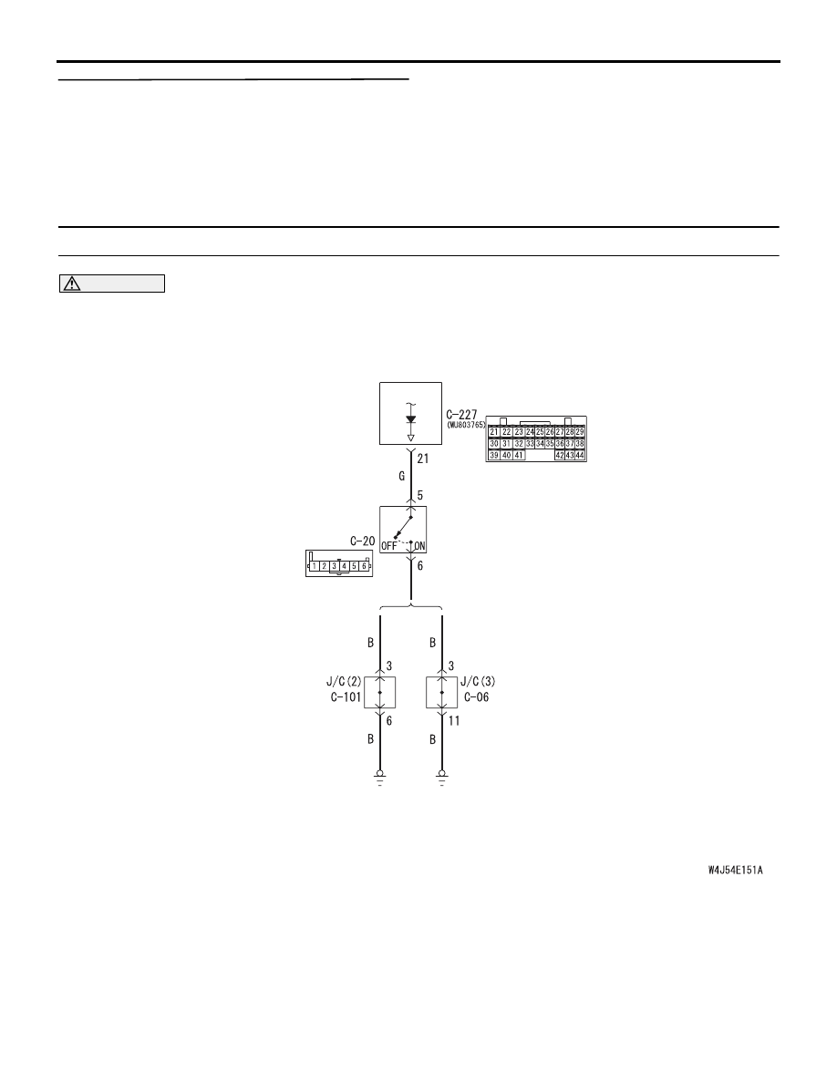
ETACS-
ECU
FOG LAMP
SWITCH
<LHD>
<RHD>
Wire colour code
B : Black LG : Light green G : Green L : Blue W : White Y : Yellow SB : Sky blue
BR : Brown O : Orange GR : Gray R : Red P : Pink V : Violet
Rear Fog Lamp Switch Input Circuit

INPUT SIGNAL PROCEDURES
SMART WIRING SYSTEM (SWS) USING SWS MONITOR
54C-278
DIAGNOSIS PROCEDURE
Step 1. Connector check: C-20 fog lamp switch
connector
Q: Is the check result normal?
YES :
Go to Step 2.
NO :
Repair the defective connector.
Step 2. Check the rear fog lamp switch.
Refer to GROUP 54A
− Rear fog lamp
.
Q: Is the check result normal?
YES :
Go to Step 3.
NO :
Replace the fog lamp switch.
Step 3. Resistance measurement at the C-20 fog
lamp switch connector
(1) Remove the fog lamp switch, and measure at the
wiring harness side.
(2) Continuity between C-20 fog lamp switch
connector terminal No.6 and body earth
OK: 2
Ω or less
Q: Is the check result normal?
YES :
Go to Step 5.
NO :
Go to Step 4.
AC310446
Harness side
AH
Connector: C-20
<LHD>
AC310456
Harness side
AI
Connector: C-20
<RHD>
AC310446
Harness side
AH
Connector: C-20
<LHD>
AC310456
Harness side
AI
Connector: C-20
<RHD>
AC301541HA
Connector C-20
(Harness side)
Нет комментариевНе стесняйтесь поделиться с нами вашим ценным мнением.
Текст