Mitsubishi Lancer Evolution IX. Manual — part 348
CHARGING SYSTEM
ENGINE ELECTRICAL
16-9
13.If the voltage reading conforms to the value in the
voltage regulation, then the voltage regulator is
operating normally.
If the voltage is not within the standard value,
there is a malfunction of the voltage regulator or of
the alternator.
14.After the test, lower the engine speed to the idle
speed.
15.Turn the ignition switch to the "LOCK" (OFF)
position.
16.Remove the M.U.T.-II/III.
17.Disconnect the negative battery cable.
18.Disconnect the ammeter and voltmeter.
19.Connect the alternator output wire to the
alternator "B" terminal.
20.Remove the special tool, and return the connector
to the original condition.
21.Connect the negative battery cable.
Voltage Regulation Table
Standard value:
Inspection terminal
Voltage regulator ambient
temperature
°C
Voltage V
Terminal "S"
−20
14.2
− 15.4
20
13.9
− 14.9
60
13.4
− 14.6
80
13.1
− 14.5
WAVEFORM CHECK USING AN OSCILLOSCOPE
M1161001200209
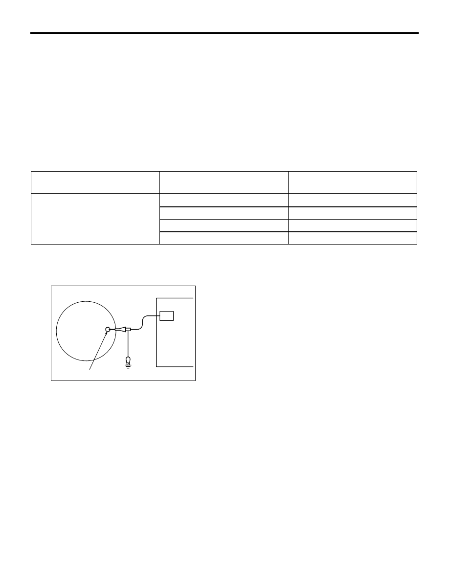
MEASUREMENT METHOD
AK100002
Alternator
"B" terminal
CH1
AC
Connect the oscilloscope special patterns pick-up to
the alternator "B" terminal.
CHARGING SYSTEM
ENGINE ELECTRICAL
16-10
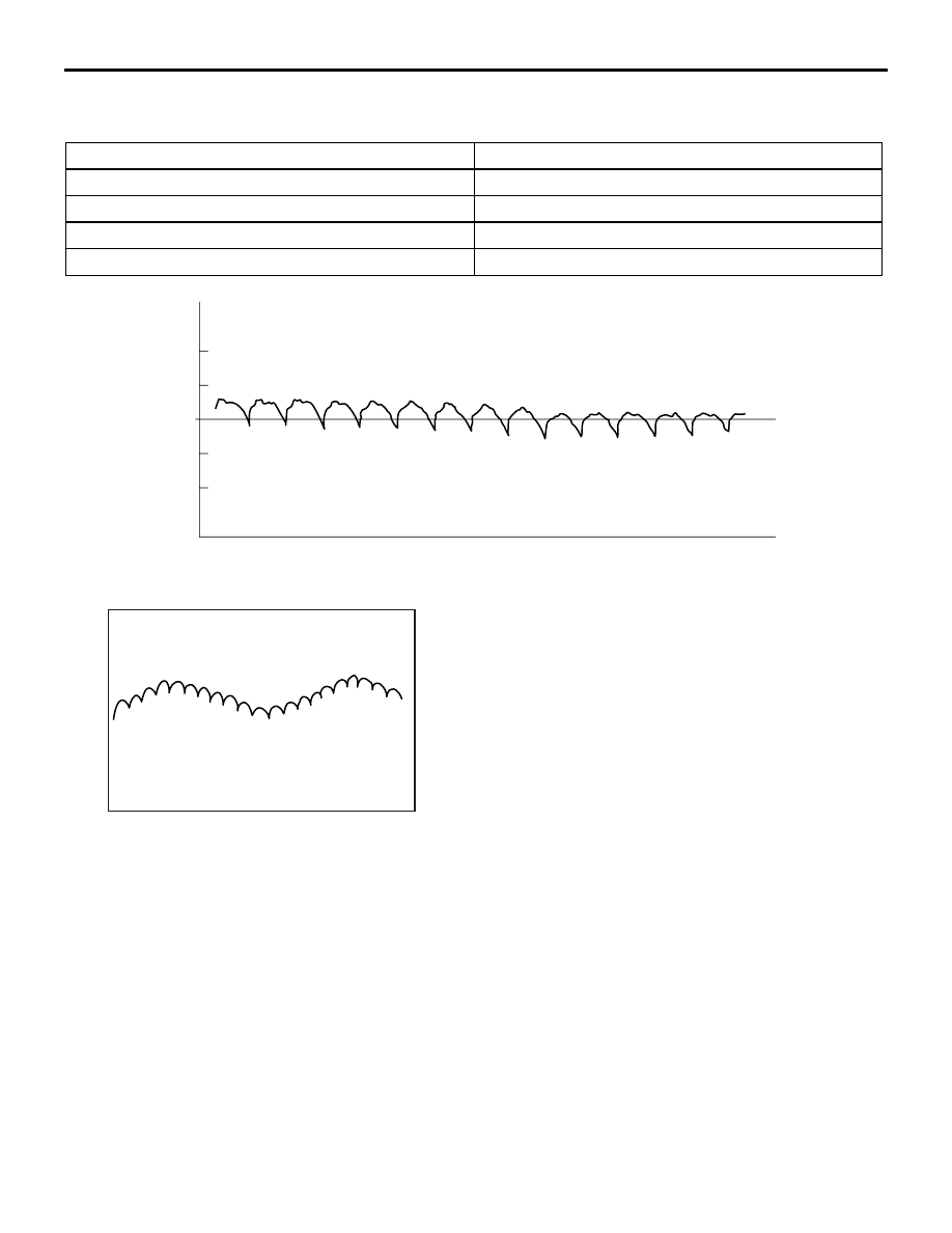
STANDARD WAVEFORM
Observation Conditions
Function
Special pattern
Pattern height
Variable
Variable knob
Adjust while viewing the waveform.
Pattern selector
Raster
Engine speed
Curb idle speed
AKX00189
0.4
(V)
0.2
0
–0.2
–0.4
Voltage at
alternator
"B" terminal
Time
AG
NOTE:
AKX00190
The voltage waveform of the alternator "B" terminal
can undulate as shown in the illustration. This wave-
form is produced when the regulator operates
according to fluctuations in the alternator load (cur-
rent), and is normal for the alternator. In addition,
when the voltage waveform reaches an excessively
high value (approximately 2 V or higher at idle), it
often indicates an open circuit due to a brown fuse
between alternator "B" terminal and battery, but not a
defective alternator.
CHARGING SYSTEM
ENGINE ELECTRICAL
16-11
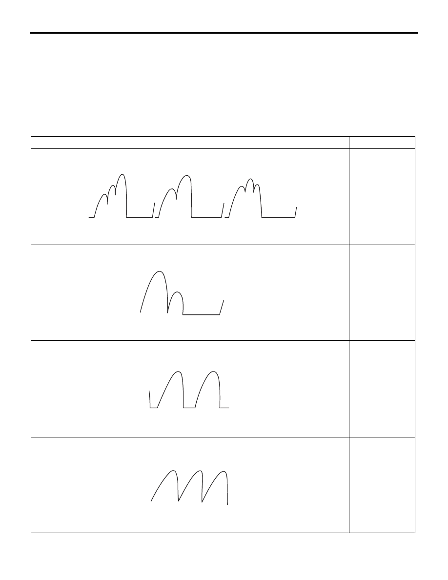
EXAMPLE OF ABNORMAL WAVEFORMS
NOTE:
.
1. The size of the waveform patterns differs largely, depending on the adjustment of the variable knob on the
oscilloscope.
2. Identification of abnormal waveforms is easier when there is a large output current (regulator is not oper-
ating). (Waveforms can be observed when the headlamps are illuminated.)
3. Check the conditions of the charging warning lamp (illuminated/not illuminated). Also, check the charging
system totally.
Abnormal waveform
Problem cause
Example 1
AKX00191
Open diode
Example 2
AKX00192
Short in diode
Example 3
AKX00193
Broken wire in
stator coil
Example 4
AKX00194
Short in stator
coil

CHARGING SYSTEM
ENGINE ELECTRICAL
16-12
ALTERNATOR ASSEMBLY
REMOVAL AND INSTALLATION
M1161001401358
CAUTION
If the vehicle is equipped with the Brembo
™ disc brake, during maintenance, take care not to contact
the caliper with tool or parts, because the caliper paint will be scratched.
Pre-removal Operation
• Under Cover Removal (Refer to GROUP 51, Front
).
• Strut Tower Bar Removal (Refer to GROUP 42, Strut
Tower Bar
• Crossmember Bar Removal (Refer to GROUP 32, Engine
Roll Stopper and Centremember
).
• Front Exhaust Pipe Assembly Removal (Refer to GROUP
15, Exhaust Pipe and Main Muffler
).
Post-installation Operation
• Front Exhaust Pipe Assembly Installation (Refer to
GROUP 15, Exhaust Pipe and Main Muffler
• Crossmember Bar Installation (Refer to GROUP 32,
Engine Roll Stopper and Centremember
).
• Strut Tower Bar Installation (Refer to GROUP 42, Strut
Tower Bar
• Drive Belt Tension Check (Refer to GROUP 11A, On-vehi-
cle Service
− Drive Belt Tension Check
).
• Under Cover Installation (Refer to GROUP 51, Front
).
Нет комментариевНе стесняйтесь поделиться с нами вашим ценным мнением.
Текст