Mitsubishi Lancer Evolution IX. Manual — part 368

DOOR
BODY
42-33
DOOR LOCK KEY CYLINDER SWITCH
CHECK <PASSENGER’S SIDE>
AC101318
3
2
1
Switch
position
Tester
connection
Specified
condition
LOCK
1
− 2
Less than 2
ohms
NEUTRAL
(OFF)
1
− 2, 2 − 3
Open circuit
UNLOCK
2
− 3
Less than 2
ohms
WINDOW GLASS RUNCHANNEL AND
DOOR OPENING WEATHERSTRIP
REMOVAL AND INSTALLATION
M1423003100449
<FRONT DOOR>
AC304409AB
Section A – A
<Front door>
Sealant: 3M ATD Part No.8633 or equivalent
Door
: Sectional view of
clip position
: Sectional view of
clip position
6
2
1
4
3
6
5
A
A
1

Waterproof film removal steps
•
Front door trim (Refer to GROUP
52A, Door trim
).
•
Speaker (Refer to GROUP 54A,
Speaker
1. Waterproof film
Door inner opening weatherstrip
removal steps
•
Scuff plate, centre pillar lower trim
and cowl side trim (Refer to GROUP
52A, Trims
).
2. Door inner opening weatherstrip
(Body side)
Door outer opening weatherstrip
removal steps
•
Front door check mounting bolt (Door
side) (Refer to
<<
A
>> >>
A
<< 3. Door outer opening weatherstrip
Door window glass runchannel
removal
4. Door window glass runchannel
Door beltline inner weatherstrip
removal steps
•
Front door trim (Refer to GROUP
52A, Door trim
).
5. Door beltline inner weatherstrip
Door beltline moulding removal steps
•
Door mirror assembly (Refer to
GROUP 51, Door mirror
•
Door window glass (Refer to
).
6. Door beltline moulding
DOOR
BODY
42-34
<REAR DOOR>
AC304418AB
Section A – A
Door
: Sectional view of
clip position
: Sectional view of
clip position
7
2
4
5
7
A
A
3
Section B – B
<Rear door>
Door
4
3
6
B
B
Sealant: 3M ATD Part No.8633 or equivalent
1
1
Waterproof film removal steps
•
Rear door trim (Refer to GROUP 52A,
Door trim
).
1. Waterproof film
Door inner opening weatherstrip
removal steps
•
Scuff plate, centre pillar lower trim
and cowl side trim (Refer to GROUP
52A, Trims
).
2. Door inner opening weatherstrip
(Body side)
Door outer opening weatherstrip
removal steps
•
Rear door check mounting bolt (Door
side) (Refer to
3. Retainer weatherstrip
<<
A
>> >>
A
<< 4. Door outer opening weatherstrip
Door window glass runchannel
removal
5. Door window glass runchannel
Door beltline inner weatherstrip
removal steps
•
Rear door trim (Refer to GROUP 52A,
Door trim
).
•
6. Door beltline inner weatherstrip
Door beltline moulding removal steps
•
Door window glass (Refer to
).
•
Stationary glass (Refer to
7. Door beltline moulding
TRUNK LID
BODY
42-35
REMOVAL SERVICE POINT
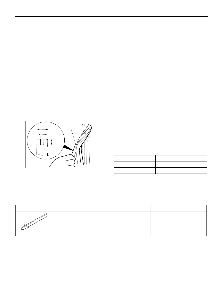
<<A>> DOOR OUTER OPENING WEATH-
ERSTRIP REMOVAL
ACX00555
15 mm
8 mm
AB
4 mm
Thickness:
1 mm
Fabricated
tool
Make a fabricated tool as shown in the illustration to
remove the door weatherstrip.
INSTALLATION SERVICE POINT
>>A<< DOOR OUTER OPENING WEATH-
ERSTRIP INSTALLATION
The clip colour identifies the left and right weather-
strips so be sure to use the colours so as to install
correctly.
Applicable side
Identification colour
Right door
Pink
Left door
Natural (White)
TRUNK LID
SPECIAL TOOL
M1421000600245
Tool
Number
Name
Use
MB991244
MB991244
Torsion bar remover and
installer
Removal and installation of
trunk lid torsion bar
ON-VEHICLE SERVICE
TRUNK LID ADJUSTMENT
M1421001000042
1. If the clearance around the trunk lid panel
assembly is not uniform and locking and
unlocking of the trunk lid is difficult, make
adjustments to the trunk lid bumpers (refer to
) and trunk lid hinges (refer to
).
2. If the clearance around the trunk lid panel
assembly is uniform, but locking and unlocking of
the trunk lid is difficult, make adjustments to the
trunk lid bumpers (refer to
) and trunk lid
striker (refer to
Door outer opening weatherstrip
removal steps (Continued)
AC202324
AC202325
AC202913
A
A
A
A
AB
Section A – A
Trunk lid panel assembly
Side outer panel
Trunk lid panel
assembly
Side outer panel
TRUNK LID
BODY
42-36
3. If there is a difference in height between the side
outer panels and the side edges of the trunk lid
panel assembly, check the trunk lid hinges and, if
necessary, replace them
4. If the clearance around the trunk lid panel
assembly is not uniform, and the trunk lid can be
locked and unlocked smoothly, make adjustments
to the trunk lid bumpers (refer to
5. If the locking and unlocking of the trunk lid still is
difficult after making the above adjustments,
adjust the trunk lid striker (Refer to
).
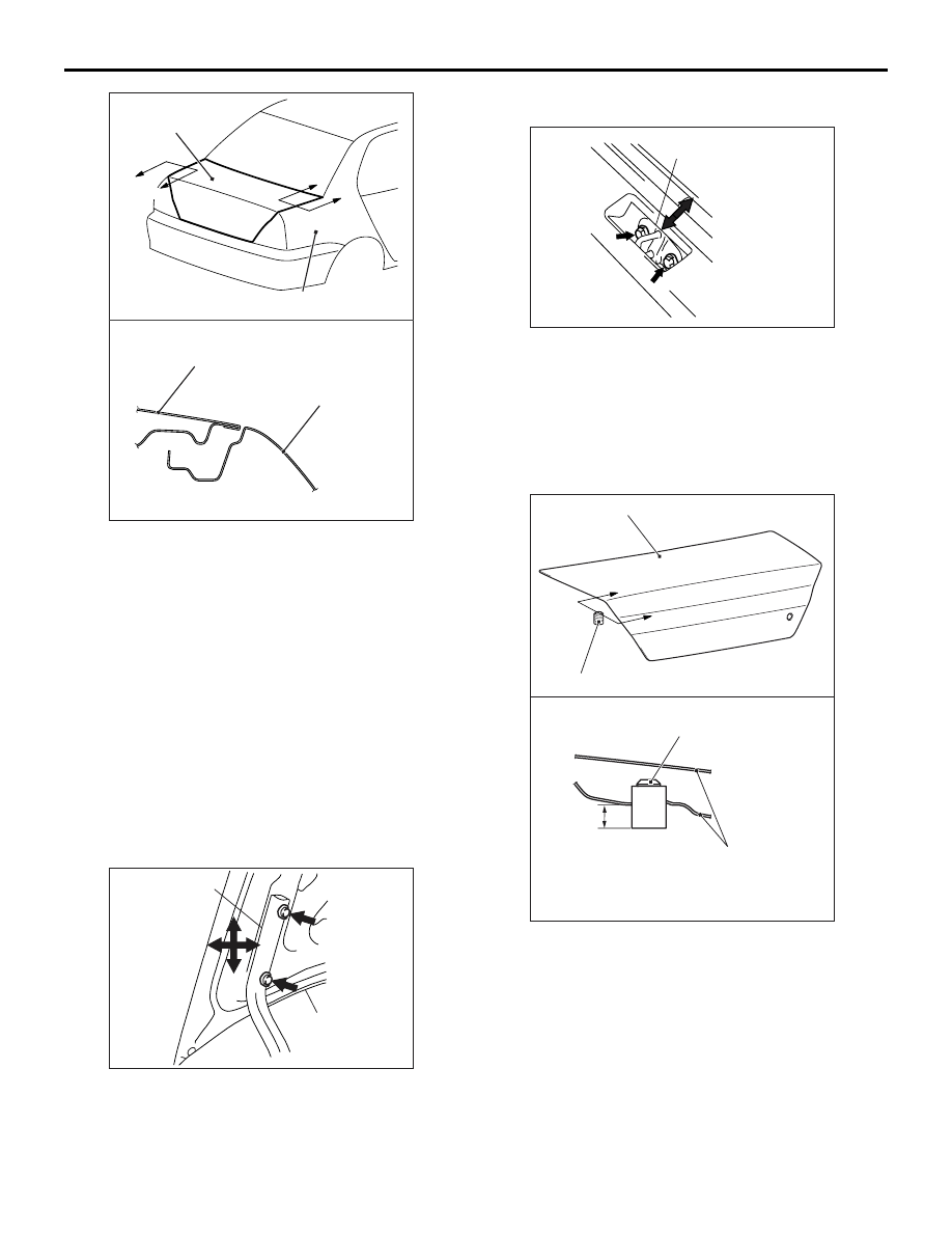
ADJUSTMENT OF CLEARANCE AROUND
TRUNK LID
M1421008100039
AC202897
Trunk lid panel
assembly
Trunk lid hinge
AB
Loosen the trunk lid panel assembly mounting bolts
and move the trunk lid panel assembly to make the
clearance around the trunk lid uniform.
TRUNK LID STRIKER ADJUSTMENT
M1421008200036
AC202898
Trunk lid striker
AB
After checking the trunk lid release cable for proper
routing, loosen the trunk lid striker mounting bolts.
Change the position of the trunk lid striker relative to
the trunk lid latch assembly so that trunk lid locking
and unlocking effort is correct.
TRUNK LID HEIGHT ADJUSTMENT
M1421008300066
AC207187
Section A – A
Trunk lid bumper
Trunk lid panel
assembly
A
A
Trunk lid bumper
Trunk lid panel assembly
AD
14 mm
Turn each trunk lid bumper until the height shown in
the drawing is reached. If the trunk lid panel height
on one side is different from that on the other side
(even after the trunk lid bumpers have been adjusted
to the height indicated in the drawing), turn the trunk
lid bumper(s) slightly to make fine adjustments to the
trunk lid panel height
NOTE: When the bumper is new, one full turn of the
trunk lid bumper changes the height approximately 3
mm. Turn it clockwise to reduce height. Turn it anti-
clockwise to increase height
Нет комментариевНе стесняйтесь поделиться с нами вашим ценным мнением.
Текст