Mitsubishi Lancer Evolution IX. Manual — part 366

DOOR
BODY
42-25
CENTRAL DOOR LOCKING SYSTEM
INSPECTION
M1427001100207
Check that the central door locking system works by
operating the key cylinders (driver’s and passenger’s
door) and the inside lock knob (driver’s door). Carry
out troubleshooting if the system does not activate.
Refer to GROUP 54B, Troubleshooting
or
GROUP 54C, Troubleshooting
DOOR OUTSIDE HANDLE PLAY CHECK
M1423001600404
AC006113AB
A
1. Check that the door outside handle play is within
the standard value range.
Standard value (A):
Front door: 2.3 mm
Rear door: 0
− 3.3 mm (target value: 1.3 mm)
2. If the door outside handle play is not within the
standard value range, check the door outside
handle or the door latch assembly. Replace, if
necessary.
DOOR INSIDE HANDLE PLAY
ADJUSTMENT
M1423001500292
AC006114
Y0705AU
AB
A
A
B
Section A – A
1. Check that the door inside handle play is within
the standard value range.
Standard value (B):
Front door: 10.4
± 9.6 mm
Rear door: 10
± 9.6 mm
2. If the door inside handle play is outside the
standard value range.
3. Remove the door trim assembly (Refer to GROUP
52A, Door trim
4. Remove the waterproof film (Refer to
AC100404 AB
Clip
Inner cable
Outer cable end
Inside handle rod
Door inside handle
5. Adjust the door inside handle play with the outer
cable end connecting the door inside handle and
inside lock cable.

DOOR
BODY
42-26
DOOR ASSEMBLY
REMOVAL AND INSTALLATION
M1423002200283
Post-installation Operation
• Door Fit Adjustment (Refer to
Y0655AU
AC006125
ACX00503
Y0652AU
5, 6
AB
<FRONT DOOR>
<REAR DOOR>
1
2
3
4
5
6
7 8
9 10
1
2
3
4
5
6
7
8
9 10
1
1.5 ± 0.5 N·m
1.5 ± 0.5 N·m
11 ± 2 N·m
11 ± 2 N·m
11 ± 2 N·m
11 ± 2 N·m
21 ± 4 N·m
27 ± 5 N·m
21 ± 4 N·m
27 ± 5 N·m
21 ± 4 N·m
27 ± 5 N·m
21 ± 4 N·m
27 ± 5 N·m
Removal
1. Damper mail
Door assembly removal steps
2. Harness connector
3. Door check connecting bolt
4. Door assembly
5. Door upper hinge
6. Door lower hinge
Striker removal steps
>>
A
<< 7. Striker
8. Striker shim
Door switch removal steps
9. Door switch cap
10. Door switch
DOOR
BODY
42-27
INSTALLATION SERVICE POINT
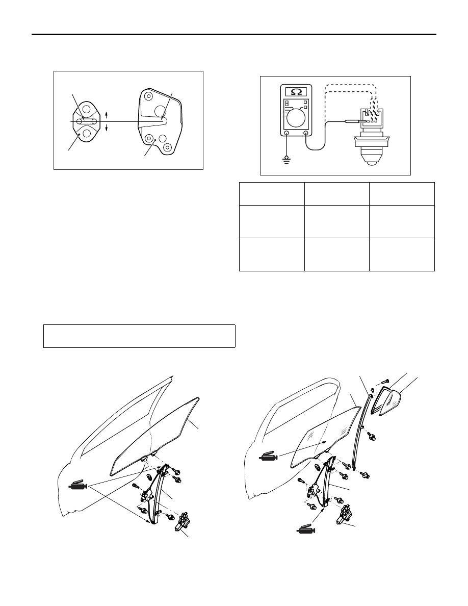
>>A<< STRIKER INSTALLATION
AC305098AB
Striker centre
Striker
Latch centre
Latch
+1.5 mm
-1.5 mm
Align the centre of the striker and latch within
±1.5
mm, and install.
INSPECTION
M1423006000322
DOOR SWITCH CHECK
AC211414
1
2
3
AC
Switch
position
Tester
connection
Specified
condition
Released (ON) 1
− switch body,
2
− switch body,
3
− switch body
Less than 2
ohms
Depressed
(OFF)
1
− switch body,
2
− switch body,
3
− switch body
Open circuit
DOOR GLASS AND REGULATOR
REMOVAL AND INSTALLATION
M1429001300467
Post-installation Operation
• Door Window Glass Adjustment (Refer to
AC212124 AB
<FRONT DOOR>
<REAR DOOR>
1
2
3
1
2
3
4
5
6

AC305108
NOTE
: Clip positions
: Claw positions
View A
B
B
B
B
C
C
C
C
C
C
C
C
Section B - B
<FRONT DOOR>
Door trim
Clip
Section C - C
AB
Door trim
Claw
7
7
7
7
A
AC305109
NOTE
: Clip positions
: Claw positions
E
E
E
E
F
F
F
F
F
F
F
F
Section E - E
View D
Door trim
Clip
Section F - F
Door trim
Claw
D
<REAR DOOR>
7
7
7
AB
7
Door window regulator assembly
removal steps
•
Door trim assembly (Refer to GROUP
52A, Door Trim
•
Waterproof film (Refer to
).
<<
A
>> >>
B
<< 1. Window regulator assembly
<<
A
>> >>
B
<< 2. Power window motor assembly
Door window glass removal steps
•
Window glass runchannel (Refer to
).
3. Door window glass
Stationary window glass removal
steps
•
Window glass runchannel (Refer to
).
•
Door beltline inner weatherstrip
(Refer to
3. Door window glass
<<
B
>> >>
A
<< 4. Centre sash upper
5. Stationary window glass
6. Stationary window weatherstrip
Power window switch removal steps
7. Power window switch panel assembly
DOOR
BODY
42-28
Нет комментариевНе стесняйтесь поделиться с нами вашим ценным мнением.
Текст