Mitsubishi Lancer Evolution IX. Manual — part 298
TRANSMISSION CASE
MANUAL TRANSMISSION OVERHAUL
22B-37
REASSEMBLY SERVICE POINTS
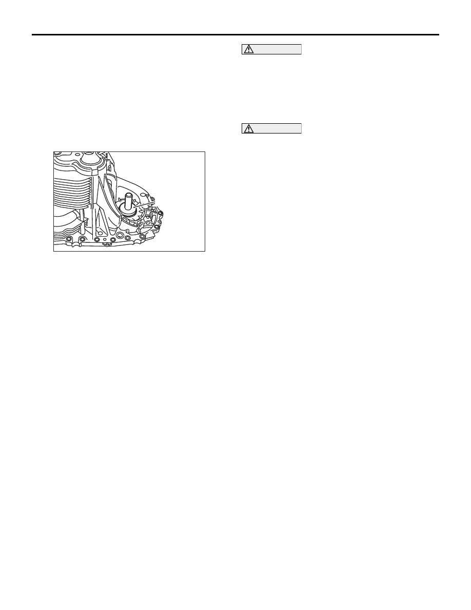
>>A<< AIR BREATHER INSTALLATION
1. Apply sealant to the entire air breather fitting
surface of the transaxle case.
Specified sealant: 3M 8513 or equivalent
2. Install the air breather on the transaxle case.
>>B<< DIFFERENTIAL OIL SEAL
INSTALLATION
AK203788
AK203788AC
MD998800
CAUTION
The oil seal is not reusable.
Using the special tool Oil seal installer (MD998800),
install the differential oil seal into the transaxle case.
>>C<< BAFFLE PLATE / OIL GUTTER
INSTALLATION
CAUTION
Apply Vaseline to the claws of the baffle plate
and oil gutter to prevent both parts from falling
off.
Install the baffle plate and oil gutter on the transaxle
case.
CENTRE DIFFERENTIAL
MANUAL TRANSMISSION OVERHAUL
22B-38
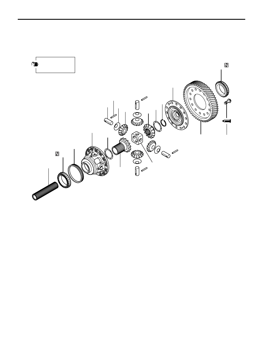
CENTRE DIFFERENTIAL
DISASSEMBLY AND REASSEMBLY
M1222010600030
AK204087AC
3
1
4
5
7
2
158 ± 7 N·m
6
8
9
10
11
12
13
14
15
16
17
Apply gear oil to
all moving parts
before installation.
Disassembly steps
>>
D
<<
1.
Center differential drive gear
<<
A
>>
>>
C
<<
2.
Taper roller bearing
>>
B
<<
3.
Center differential flange
>>
B
<<
4.
Snap ring
>>
B
<<
5.
Front output shaft
>>
B
<<
6.
Spacer
>>
B
<<
7.
Side gear
>>
B
<<
8.
Lock pin
>>
B
<<
9.
Pinion shaft
>>
B
10. Pinion shaft holder
>>
B
11. Pinion
>>
B
12. Washer
>>
B
13. Side gear
>>
B
14. Spacer
<<
B
>>
>>
A
15. Taper roller bearing
16. Speedometer drive gear
17. Differential case
Disassembly steps (Continued)
CENTRE DIFFERENTIAL
MANUAL TRANSMISSION OVERHAUL
22B-39
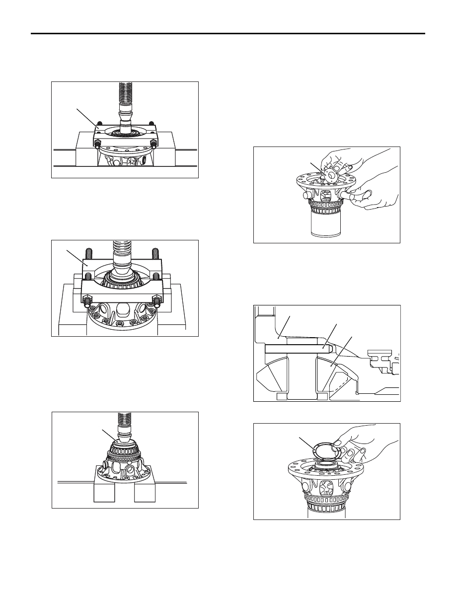
DISASSEMBLY SERVICE POINTS
<<A>> TAPER ROLLER BEARING
REMOVAL
AK203789
AK203789AC
MD998801
Using the special tool Bearing remover (MD998801),
remove the taper roller bearing.
<<B>> TAPER ROLLER BEARING
REMOVAL
AK203790
AK203790 AC
MD998801
Using the special tool Bearing remover (MD998801),
remove the taper roller bearing.
REASSEMBLY SERVICE POINTS
>>A<< TAPER ROLLER BEARING
INSTALLATION
AK203791
AK203791AC
MB990936
Using the special tool installer adapter (MB990936),
install the taper roller bearing.
>>B<< SPACER / SIDE GEAR / WASHER /
PINION / PINION SHAFT HOLDER /
PINION SHAFT / LOCK PIN / FRONT
OUTPUT SHAFT / SNAP RING / CENTER
DIFFERENTIAL FLANGE INSTALLATION
1. Install the spacer on each side gear, then install
the side gears into the center differential case.
NOTE: When installing new side gears, use spac-
ers of a medium thickness (0.66
−
0.73 mm).
AK203793AC
Washer
2. Install a washer on the backside of each pinion.
Simultaneously engage all four pinions with the
side gears, and install them into position while
rotating, then install the pinion shaft holder.
3. Insert the pinion shafts into the pinions.
AK204147AC
Differntial case
Lock pin
Pinion
4. Install the lock pins as indicated in the illustration.
AK203794 AC
Spacer
5. Insert the front output shaft into each side gear,
then install the snap ring.
6. Install the spacer on each side gear. Next, install
the side gears into the center differential case.

CENTRE DIFFERENTIAL
MANUAL TRANSMISSION OVERHAUL
22B-40
NOTE: When installing new side gears, use spac-
ers of a medium thickness (0.66
−
0.73 mm).
AK203796AC
Match
marks
7. Install the center differential flange on the
differential case while aligning the match marks.
Secure it temporarily in place using machine
screws in four places.
AK203797
8. Measure the backlash between the side gears
and pinions.
Standard value: 0.025
− 0.150 mm
9. If the backlash does not fall within the standard
value range, select other appropriate spacers,
replace the existing spacers with them, and
measure the backlash once again.
NOTE: Adjust the backlash on each side so that it
is equal to the backlash on the other side.
>>C<< TAPER ROLLER BEARING
INSTALLATION
AK203792
AK203792 AC
MB990936
Using the special tool Installer adapter
(MB9900936), install the taper roller bearing.
>>D<< CENTER DIFFERENTIAL DRIVE
GEAR INSTALLATION
AK204150
AK204150AC
1. Apply sealant to the entire threaded part on the
bolts.
Specified sealant: 3M STUD Locking No.
4170 or equivalent
AK204149
AK204149AC
4
5
6
1
2
3
7
8
9
14
11
12
13
10
2. Tighten bolts to the specified torque of 158
± 7
N
⋅m in the order indicated in the illustration.
Нет комментариевНе стесняйтесь поделиться с нами вашим ценным мнением.
Текст