Mitsubishi Lancer Evolution IX. Manual — part 318

DIFFERENTIAL CARRIER ASSEMBLY
REAR AXLE
27-47
Lubrication and Adhesive Points
AC301834 AB
Grease: Vaseline
Sealant: 3M ATD Part No.8661 or
equivalent
Sealant: 3M ATD Part No.8661 or
equivalent

DIFFERENTIAL CARRIER ASSEMBLY
REAR AXLE
27-48
DISASSEMBLY SERVICE POINTS
<<A>> SELF-LOCKING NUT REMOVAL
AC310763AB
MB990850
Use special tool end yoke holder (MB990850) to hold
the companion flange, and then remove the compan-
ion flange self-locking nut.
REASSEMBLY SERVICE POINTS
>>A<< OIL SEAL PRESS-FITTING
AC310759AB
MD998829
MD998813
MD998812
1. Use the following special tools to press-fit the oil
seal.
• Installer cap (MD998812)
• Installer 100 (MD998813)
• Installer adaptor (MD998829)
2. Apply specified grease to the oil seal lip and
driveshaft oil seal seating area.
Specified grease: Vaseline
>>B<< OIL SEAL PRESS-FITTING
AC102740
MB990938
MB991115
AC
1. Use the following special tools to press-fit the oil
seal.
• Installer bar (MB990938)
• Oil seal installer (MB991115)
2. Apply multi-purpose grease to the oil seal lip and
driveshaft oil seal seating area.
>>C<< SELF-LOCKING NUT
INSTALLATION
AC310764 AB
MB990850
Tighten the companion flange self-locking nut to the
specified torque while holding the companion flange
with special tool end yoke holder (MB990850).
Tightening torque: 186
± 29 N⋅m

DIFFERENTIAL CARRIER ASSEMBLY
REAR AXLE
27-49
REMOVAL AND INSTALLATION
M1272005400035
CAUTION
• When connecting the return hose and suction hose, do not apply lubricant.
•
Pre-removal Operation
• Trunk Room Side Trim Removal (Refer to GROUP
52A
−Trims
).
• Hydraulic Piping Fluid Draining
Post-installation Operation
• Hydraulic Piping Fluid Filling (Refer to
).
• Hydraulic Piping Bleeding (Refer to
).
• Trunk Room Side Trim Installation (Refer to GROUP
52A
−Trims
).
AC310846 AC
12 ± 2 N·m
18 ± 2 N·m
6
34 ± 5 N·m*
26 ± 4 N·m**
12 ± 2 N·m
24 ± 4 N·m
NOTE:
*: Thread is not lubricated
**: Thread is lubricated
18 ± 2 N·m
10
2
7
5
1
34 ± 5 N·m*
26 ± 4 N·m**
12 ± 2 N·m
3
4
9
11
12 ± 2 N·m
12 ± 2 N·m
21 ± 3 N·m
8
Removal steps
1. Dust guard
2. Reservoir hose assembly and
hydraulic unit connection
3. Hydraulic unit hose assembly and
hydraulic unit connection
4. Transfer connector assembly and
hydraulic unit connection
5. Hydraulic unit bracket assembly
mounting bolt
>>
B
<< 6. Hydraulic unit assembly
7. Hydraulic unit bracket
•
Stabilizer bar to differential support
arm connection (Refer to GROUP 34,
Stabilizer bar
).
•
Differential support arm (Refer to
).
<<
A
>>
8. Hydraulic unit hose assembly
9. Transfer connector assembly
>>
A
<< 10. Reservoir hose assembly
11. Oil reservoir
No foreign matter should be allowed in the hydraulic piping and joints.
Removal steps (Continued)
DIFFERENTIAL CARRIER ASSEMBLY
REAR AXLE
27-50
REMOVAL SERVICE POINTS
<<A>> HYDRAULIC UNIT HOSE ASSEM-
BLY REMOVAL
AC310847AB
Pipe
Hose
1. Disconnect the hydraulic unit side pipe and hose.
AC310848AB
Hydraulic unit
hose assembly
Differential
support arm
2. Pull down the differential support arm, remove the
hydraulic unit hose assembly.
INSTALLATION SERVICE POINTS
>>A<< RESERVOIR HOSE ASSEMBLY
INSTALLATION
AC310850 AB
Nipple
Reservoir hose
assembly
Positioning
spool
Insert the reservoir hose assembly to the positioning
spool.
>>B<< HYDRAULIC UNIT ASSEMBLY
INSTALLATION
AC310851AB
Hook
Rear floor
side member
Hook the hydraulic unit assembly hook to the rear
floor side member and tighten the hydraulic unit
assembly mounting bolt.
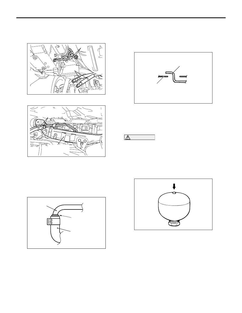
HYDRAULIC UNIT DISPOSAL
M1272008300026
CAUTION
• The hydraulic unit has its accumulator filled
with a high-pressure gas. Never throw it into a
fire. Also, never attempt to disassemble,
press, weld or melt it.
•
AC310849 AB
When drilling a hole in the accumulator, be
sure to wear safety goggles since drill chips
may blow out together with the gas.
When discarding the hydraulic unit, drill a hole in the
accumulator at the illustrated position beforehand in
order to release the inside gas.
Нет комментариевНе стесняйтесь поделиться с нами вашим ценным мнением.
Текст