Mitsubishi Lancer Evolution IX. Manual — part 319
37-1
GROUP 37
CONTENTS
GENERAL INFORMATION . . . . . . . .
SERVICE SPECIFICATIONS. . . . . . .
LUBRICANTS . . . . . . . . . . . . . . . . . .
SEALANTS . . . . . . . . . . . . . . . . . . . .
SPECIAL TOOLS. . . . . . . . . . . . . . . .
ON-VEHICLE SERVICE. . . . . . . . . . .
STEERING WHEEL FREE PLAY CHECK .
STEERING ANGLE CHECK . . . . . . . . . . . .
TIE ROD END BALL JOINT TURNING
TORQUE CHECK . . . . . . . . . . . . . . . . . . . .
STATIONARY STEERING EFFORT CHECK
STEERING WHEEL RETURN TO CENTRE
CHECK . . . . . . . . . . . . . . . . . . . . . . . . . . . .
DRIVE BELT TENSION CHECK. . . . . . . . .
FLUID LEVEL CHECK . . . . . . . . . . . . . . . .
FLUID REPLACEMENT . . . . . . . . . . . . . . .
POWER STEERING SYSTEM AIR
BLEEDING . . . . . . . . . . . . . . . . . . . . . . . . .
OIL PUMP PRESSURE TEST . . . . . . . . . .
POWER STEERING PRESSURE SWITCH
CHECK . . . . . . . . . . . . . . . . . . . . . . . . . . . .
TIE ROD END BALL JOINT DUST COVER
CHECK . . . . . . . . . . . . . . . . . . . . . . . . . . . .
STEERING COLUMN SHAFT ASSEMBLY
SHOCK ABSORBING MECHANISM CHECK
STEERING WHEEL*. . . . . . . . . . . . . .
REMOVAL AND INSTALLATION . . . . . . . .
STEERING COLUMN SHAFT
ASSEMBLY* . . . . . . . . . . . . . . . . . . . .
REMOVAL AND INSTALLATION . . . . . . . .
DISASSEMBLY AND REASSEMBLY . . . . .
POWER STEERING GEAR BOX AND
LINKAGE* . . . . . . . . . . . . . . . . . . . . . .
REMOVAL AND INSTALLATION . . . . . . . .
INSPECTION. . . . . . . . . . . . . . . . . . . . . . . .
DISASSEMBLY AND REASSEMBLY . . . . .
TIE ROD END BALL JOINT DUST COVER
REPLACEMENT . . . . . . . . . . . . . . . . . . . . .
POWER STEERING OIL PUMP
ASSEMBLY. . . . . . . . . . . . . . . . . . . . .
REMOVAL AND INSTALLATION . . . . . . . .
DISASSEMBLY AND REASSEMBLY . . . . .
INSPECTION. . . . . . . . . . . . . . . . . . . . . . . .
POWER STEERING HOSES*. . . . . . .
REMOVAL AND INSTALLATION . . . . . . . .
WARNINGS REGARDING SERVICING OF SUPPLEMENTAL RESTRAINT SYSTEM (SRS) EQUIPPED VEHICLES
WARNING
•
Improper service or maintenance of any component of the SRS, or any SRS-related component, can lead to
personal injury or death to service personnel (from inadvertent firing of the air bag) or to the driver and
passenger (from rendering the SRS inoperative).
•
Service or maintenance of any SRS component or SRS-related component must be performed only at an
authorized MITSUBISHI dealer.
•
MITSUBISHI dealer personnel must thoroughly review this manual, and especially its GROUP 52B - Supplemental
Restraint System (SRS) before beginning any service or maintenance of any component of the SRS or any
SRS-related component.
NOTE
The SRS includes the following components: SRS-ECU, SRS warning lamp, air bag module, clock spring, and interconnecting
wiring. Other SRS-related components (that may have to be removed/installed in connection with SRS service or maintenance)
are indicated in the table of contents by an asterisk (*).
GENERAL INFORMATION
POWER STEERING
37-2
GENERAL INFORMATION
M1372000100434
Power steering has been adopted in all vehicles to
make the steering system easier to handle.
FEATURES
• The system has been equipped with the MOMO
leather 3-spoke-type steering wheel with built-in
SRS air bag.
• A steering column with a shock absorbing mech-
anism and a tilt steering mechanism has been
adopted.
• Integral-type rack and pinion gear with high rigid-
ity and excellent response has been adopted.
• A variable capacity pump has been adopted to
reduce power losses and improve fuel economy.
• Improved the cooling efficiency of power steering
fluid by adopting a cooler tube to the fluid line.
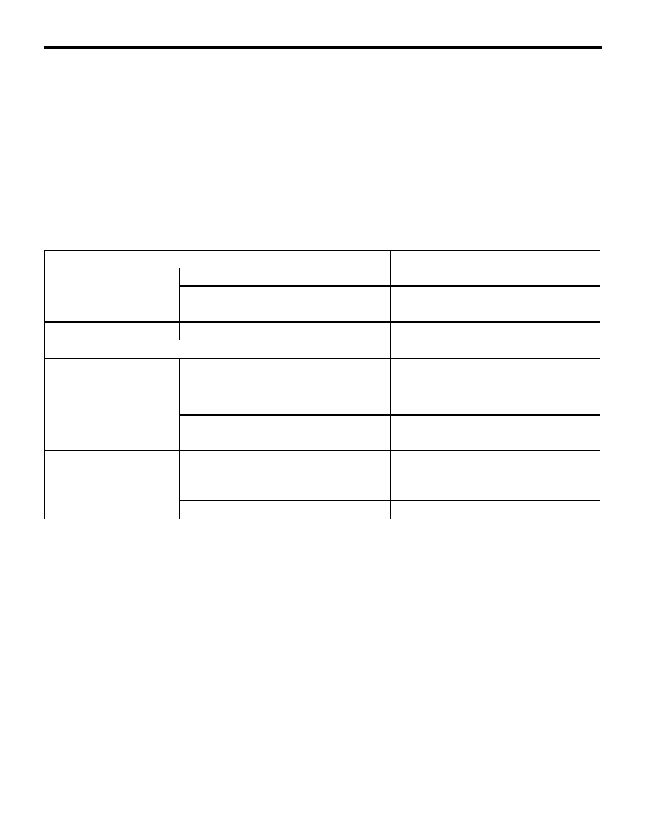
SPECIFICATIONS
Item
Specification
Steering wheel
Type
MOMO leather-wrapped 3-spoke type
Outside diameter mm
365
Maximum number of turns
2.1
Steering column
Column mechanism
Tilt steering
Power steering type
Integral type
Oil pump
Type
Variable capacity type (vane pump)
Basic delivery rate cm
3
/rev.
9.6
Relief pressure MPa
8.3
− 9.0
Reservoir type
Separate type
Pressure switch
Equipped
Steering gear
Type
Rack and pinion
Stroke ratio (Rack stroke/Steering
wheel maximum turning radius)
68.61
Rack stroke mm
146
GENERAL INFORMATION
POWER STEERING
37-3
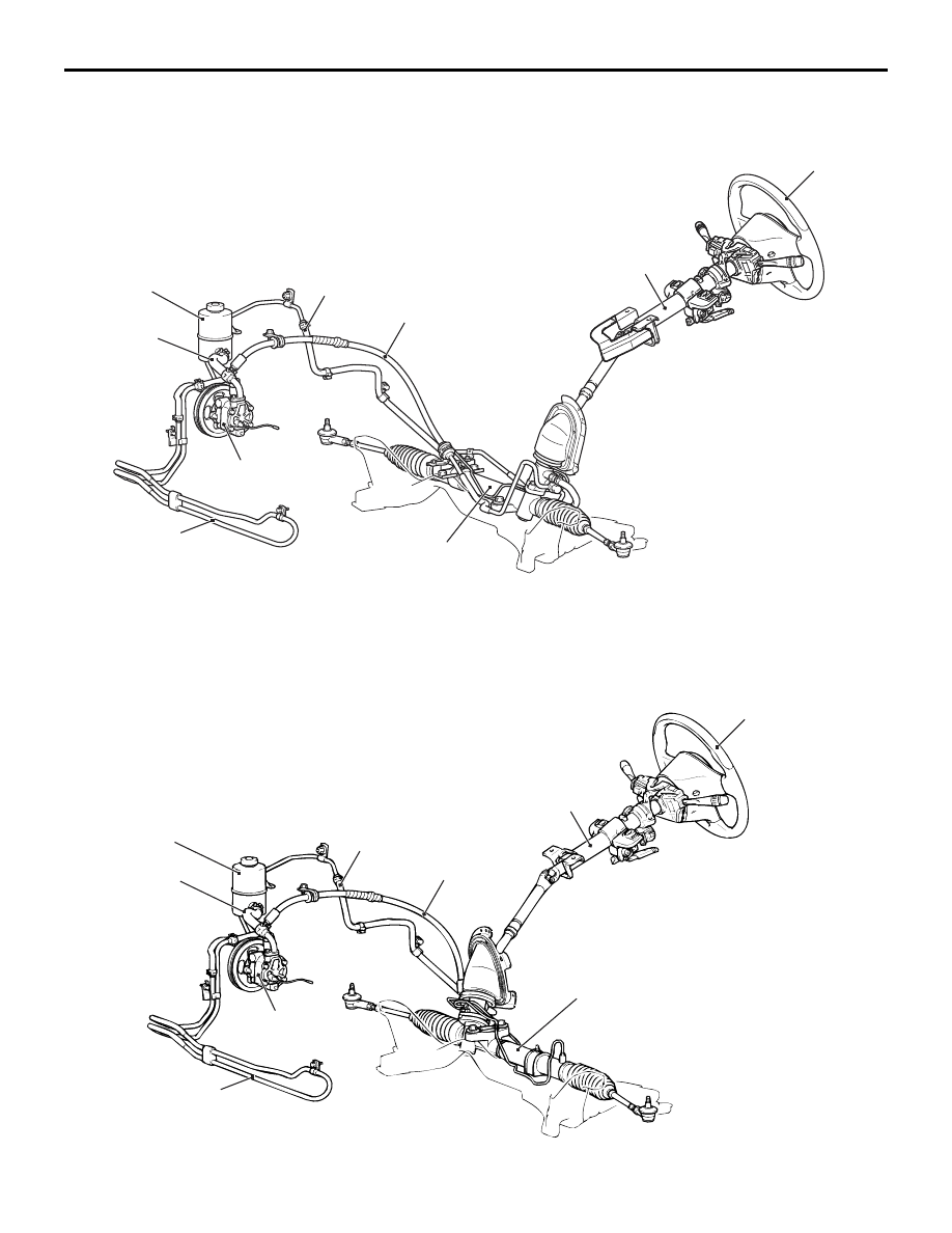
CONSTRUCTION DIAGRAM
LH drive vehicles
AC310660AB
Steering wheel
Steering column and shaft
Cooler tube
Suction hose
Pressure hose
Oil pump assembly
Steering gear and linkage
Return hose
Reservoir tank
RH drive vehicles
AC310702 AC
Steering wheel
Steering column and shaft
Cooler tube
Suction hose
Pressure hose
Oil pump assembly
Steering gear and linkage
Return hose
Reservoir tank
SERVICE SPECIFICATIONS
POWER STEERING
37-4
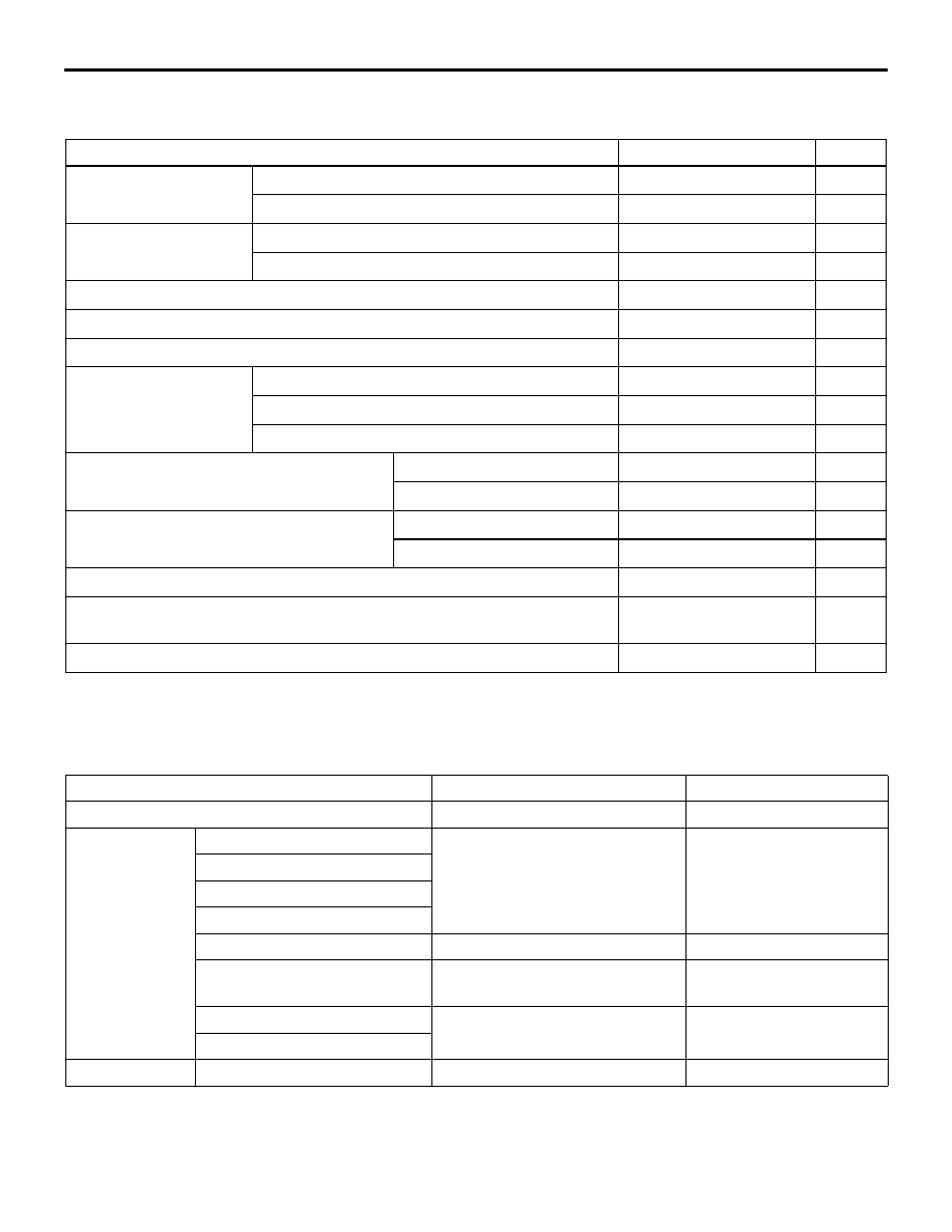
SERVICE SPECIFICATIONS
M1372000300502
Item
Standard value
Limit
Steering wheel free
play mm
With engine running
−
30
With engine stopped
10 or less
−
Steering angle
Inner wheel
31
°45' ± 1°30'
−
Outer wheel (reference)
27
°15'
−
Toe-in
0
± 2
−
Tie rod end ball joint turning torque N
⋅m
1.0
− 3.0
−
Stationary steering effort N [Fluctuation allowance N]
32 or less [6.0 or less]
−
Oil pump pressure
MPa (750
± 100 r/min).
Oil pump relief pressure
8.3
− 9.0
−
Pressure under no-load conditions
0.2
− 0.8
−
Steering gear retention hydraulic pressure
8.3
− 9.0
−
Oil pressure switch operating pressure
MPa
OFF
→ ON
1.8
− 2.4
−
ON
→ OFF
1.0
− 2.4
−
Total pinion torque N
⋅m
Total rotation torque
0.8
− 1.8
−
Torque variation
0.49 or less
−
Tie rod swing resistance N [Tie rod swing torque N
⋅m]
8
− 27 [1.5 − 4.9]
−
Opening dimension of special tool boot band crimping tool (MB991561)
mm
2.9
−
Band crimped width mm
2.4
− 2.8
−
LUBRICANTS
M1372000400435
Item
Specified lubricant
Quantity
Power steering fluid
ATF DEXRON III or DEXRON II Approximately 1.0 L
Steering gear
Bearing
ATF DEXRON III or DEXRON II As required
O-ring and seal ring
Oil seal
Special tool (MB991214)
Bellows
Silicon grease
As required
Tie rod end ball joint
Multipurpose grease SAE J310,
NLGI No.2 or equivalent
As required
Pinion and valve assembly
Repair kit grease
As required
Rock assembly
Oil pump
O-ring
ATF DEXRON III or DEXRON II As required
Нет комментариевНе стесняйтесь поделиться с нами вашим ценным мнением.
Текст