Mitsubishi Lancer Evolution IX. Manual — part 664
13B-1
GROUP 13B
CONTENTS
GENERAL INFORMATION . . . . . . . .
ON-VEHICLE SERVICE. . . . . . . . . . .
FUEL PUMP OPERATION CHECK . . . . . .
FUEL PUMP MODULE REPLACEMENT . .
FUEL GAUGE UNIT CHECK . . . . . . . . . . .
FUEL GAUGE UNIT REPLACEMENT . . . .
FUEL TANK . . . . . . . . . . . . . . . . . . . .
REMOVAL AND INSTALLATION . . . . . . . .
FUEL PUMP MODULE DISASSEMBLY AND
REASSEMBLY . . . . . . . . . . . . . . . . . . . . . .
GENERAL INFORMATION
FUEL SUPPLY
13B-2
GENERAL INFORMATION
M1135000100480
• The fuel tank is located under the floor of the rear
seats to provide increased protection and more
luggage space.
• A fuel tank safety valve is used to prevent fuel
from leaking out in case of a collision.
• A fuel pump module, including fuel pump, fuel fil-
ter assembly and fuel gauge unit (main), is uti-
lized to reduce weight and improve serviceability.
ON-VEHICLE SERVICE
FUEL PUMP OPERATION CHECK
M1135001000204
Refer to GROUP 13A, On-vehicle Service
FUEL PUMP MODULE REPLACEMENT
M1135004900369
1. Remove the rear seat cushion assembly. (Refer to
GROUP 52A, Rear Seat Assembly
).
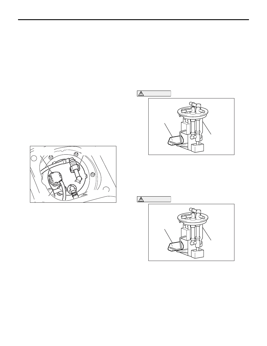
2. Remove the service hole cover.
AC210801AB
Suction
hose
Fuel high-
pressure hose
Harness
connector
Fuel return
hose
3. Disconnect the harness connector.
NOTE: Check the fuel pump (Refer to GROUP
13A, On-vehicle Service
). If defective,
replace the fuel pump, which is incorporated in
the fuel pump module.
4. Disconnect fuel high-pressure hose, suction hose
and fuel return hose.
AC211368
Float
Fuel pump
module
AB
CAUTION
When withdrawing the fuel pump module from
the fuel tank, be careful not damage the module
unit and the float.
5. Unscrew the mounting nuts to remove the fuel
pump module.
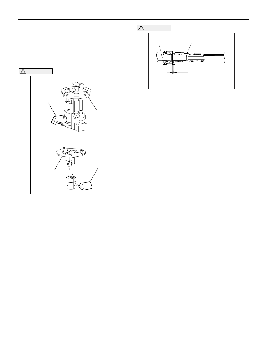
6. Replace the fuel pump (Refer to
AC211368
Float
Fuel pump
module
AB
CAUTION
When installing the fuel pump module into the
fuel tank, be careful not damage the module unit
and the float.
7. Install the fuel pump module. Tighten the
mounting nuts to the specified torque.
Tightening torque: 2.5
± 0.5 N⋅m

AC100963 AC
Fuel
high-pressure
hose
Corresponding
side
3.0 mm
ON-VEHICLE SERVICE
FUEL SUPPLY
13B-3
CAUTION
Snap the fuel high-pressure hose one-touch joint
into place, then pull back slightly on the hose to
assure it is secure. However, the connection
should have a play of approximately 3.0 mm.
8. Connect the harness connector, fuel
high-pressure hose, suction hose and fuel return
hose.
9. Replace the service hole cover.
10.Install the rear seat cushion assembly (Refer to
GROUP 52A, Rear Seat Assembly
).
FUEL GAUGE UNIT CHECK
M1135003100401
Refer to GROUP 54A, Combination Meter Assembly
and Vehicle Speed Sensor
− On-vehicle Service
.
FUEL GAUGE UNIT REPLACEMENT
M1135001400428
1. Remove the rear seat cushion assembly. (Refer to
GROUP 52A, Rear Seat Assembly
).
2. Remove the service hole cover.
Y2014AU
AC310596
AC310872AB
Suction
hose
Fuel high-
pressure hose
Fuel return
hose
Suction
hose
<Fuel gauge unit (Sub)>
<Fuel gauge unit (Main)>
Fuel pump
module
Fuel pipe and
gauge assembly
Harness
connector
Harness
connector
3. Disconnect the harness connector, fuel
high-pressure hose, suction hose and fuel return
hose.
AC310597
Float
Fuel pump
module
AB
Float
Fuel pipe
and gauge
assembly
CAUTION
When withdrawing the fuel pump module or fuel
pipe and gauge assembly from the fuel tank, be
careful not damage the sensor unit and the float.
ON-VEHICLE SERVICE
FUEL SUPPLY
13B-4
4. Unscrew the mounting nuts to remove the fuel
pump module or fuel pipe and gauge assembly.
NOTE: Check the fuel gauge unit (Refer to
GROUP 54A, Combination Meter Assembly and
Vehicle Speed Sensor
−
On-vehicle Service
). If defective, replace it. (Refer to
AC310597
Float
Fuel pump
module
AB
Float
Fuel pipe
and gauge
assembly
CAUTION
When inserting the fuel pump module or fuel pipe
and gauge assembly into the fuel tank, be careful
not damage the sensor unit and the float.
5. Install the fuel pump module or fuel pipe and
gauge assembly. Tighten the mounting nuts to the
specified torque.
Tightening torque: 2.5
± 0.5 N⋅m
AC100963 AC
Fuel
high-pressure
hose
Corresponding
side
3.0 mm
CAUTION
Snap the fuel high-pressure hose one-touch joint
into place, then pull back slightly on the hose to
assure it is secure. However, the connection
should have a play of approximately 3.0 mm.
6. Connect the harness connector, fuel
high-pressure hose, suction hose and fuel return
hose.
7. Replace the service hole cover.
8. Install the rear seat cushion assembly. (Refer to
GROUP 52A, Rear Seat Assembly
).
Нет комментариевНе стесняйтесь поделиться с нами вашим ценным мнением.
Текст