Mitsubishi Lancer Evolution IX. Manual — part 663
AC210547 AB
39 ± 5 N·m
49 ± 10 N·m
167 ± 9 N·m
108 ± 10 N·m
21 ± 4 N·m
25 ± 4 N·m
186 ± 10 N·m*²
39 ± 5 N·m
52 ± 7 N·m*¹
45 ± 5 N·m*¹
70 ± 10 N·m
8
N
12 ± 2 N·m
21 ± 4 N·m
12 ± 2 N·m
57 ± 7 N·m
18 ± 2 N·m
16
15
14
13
1
9
7
6
5
4
3
2
N
15 ± 3 N·m
12
10
11
N
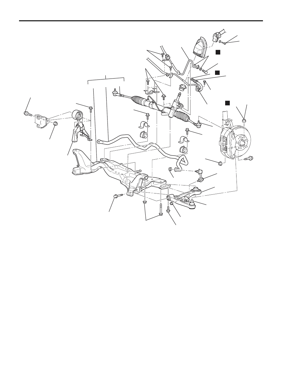
Removal steps
1.
Lower arm and knuckle
connection
2.
Stabilizer link
<<
A
>>
3.
Lower arm assembly
4.
Steering shaft assembly and gear
box connecting bolt
5.
Engine rear roll stopper rod bolt
6.
Engine rear roll stopper rod and
bracket assembly
7.
Return hose and return pipe
8.
O-ring
9.
Pressure hose connection
10. Gaskets
11. Self-locking nut
<<
B
>>
12. Tie rod end and knuckle
connection
<<
C
>>
13. Front axle No.1 crossmember
assembly
>>
A
<< 14. Stabilizer bar
15. Steering gear and linkage
16. Front axle No.1 crossmember
CROSSMEMBER
POWER PLANT MOUNT
32-11
Removal steps (Continued)
CROSSMEMBER
POWER PLANT MOUNT
32-12
<RH drive vehicles>
CAUTION
• Before removing the steering wheel and air bag module assembly, always refer to GROUP 52B -
Service Precautions, Air bag Module and Clock Spring. Also, set the front wheels so that they are
facing straight forward, and remove the ignition key. If you fail to do this, the SRS clock spring will
be damaged, causing the SRS air bag to be inoperative and serious injury.
• *
1
: Indicates parts which should be initially tightened, and then fully tightened after placing the
vehicle horizontally and loading the full weight of the engine on the vehicle body.
• *
2
: Indicates parts which should be temporarily tightened, and then fully tightened with the vehicle
on the ground in the unladen condition.
• If the vehicle is equipped with the Brembo™ disc brake, during maintenance, take care not to con-
tact the parts or tools to the caliper because the paint of caliper will be scratched.
Pre-removal and Post-installation Operation
• Under Cover Removal (Refer to GROUP 51, Front
).
• Front Axle Crossmember Bar, Front Suspension Center-
member Removal (Refer to
• Front Exhaust Pipe Removal (Refer to GROUP 15,
Exhaust Pipe and Main Muffler
• Steering Wheel Air Bag Module Assembly Removal
(Refer to GROUP 37, Steering Wheel
• Power Steering Fluid Draining (Refer to GROUP 37,
On-vehicle Service
− Fluid Replacement
Pre-removal and Post-installation Operation
• Front Exhaust Pipe Installation (Refer to GROUP 15,
Exhaust Pipe and Main Muffler
• Front Axle Crossmember Bar, Front Suspension Center-
member Installation (Refer to
• Steering Wheel Air Bag Module Assembly Installation
(Refer to GROUP 37, Steering Wheel
• Power Steering Fluid Supplying (Refer to GROUP 37,
On-vehicle Service
− Fluid Replacement
• Power Steering Fluid Line Bleeding (Refer to GROUP 37,
On-vehicle Service
− Power Steering System Air Bleeding
• Press the dust cover with a finger to check whether the
dust cover cracked or damaged.
• Checking Steering Wheel Position with Wheels Straight
Ahead.
• Front Wheel Alignment Check and Adjustment (Refer to
GROUP 37, On-vehicle Service
− Steering Angle Check
).
• Under Cover Installation (Refer to GROUP 51, Front
).
AC310965AB
39 ± 5 N·m
49 ± 10 N·m
167 ± 9 N·m
108 ± 10 N·m
21 ± 4 N·m
25 ± 4 N·m
186 ± 10 N·m*²
39 ± 5 N·m
52 ± 7 N·m*¹
45 ± 5 N·m*¹
70 ± 10 N·m
5
N
21 ± 4 N·m
57 ± 7 N·m
18 ± 2 N·m
16
15
14
12
1
7
6
11
3
2
N
15 ± 3 N·m
10
9
N
4
8
13
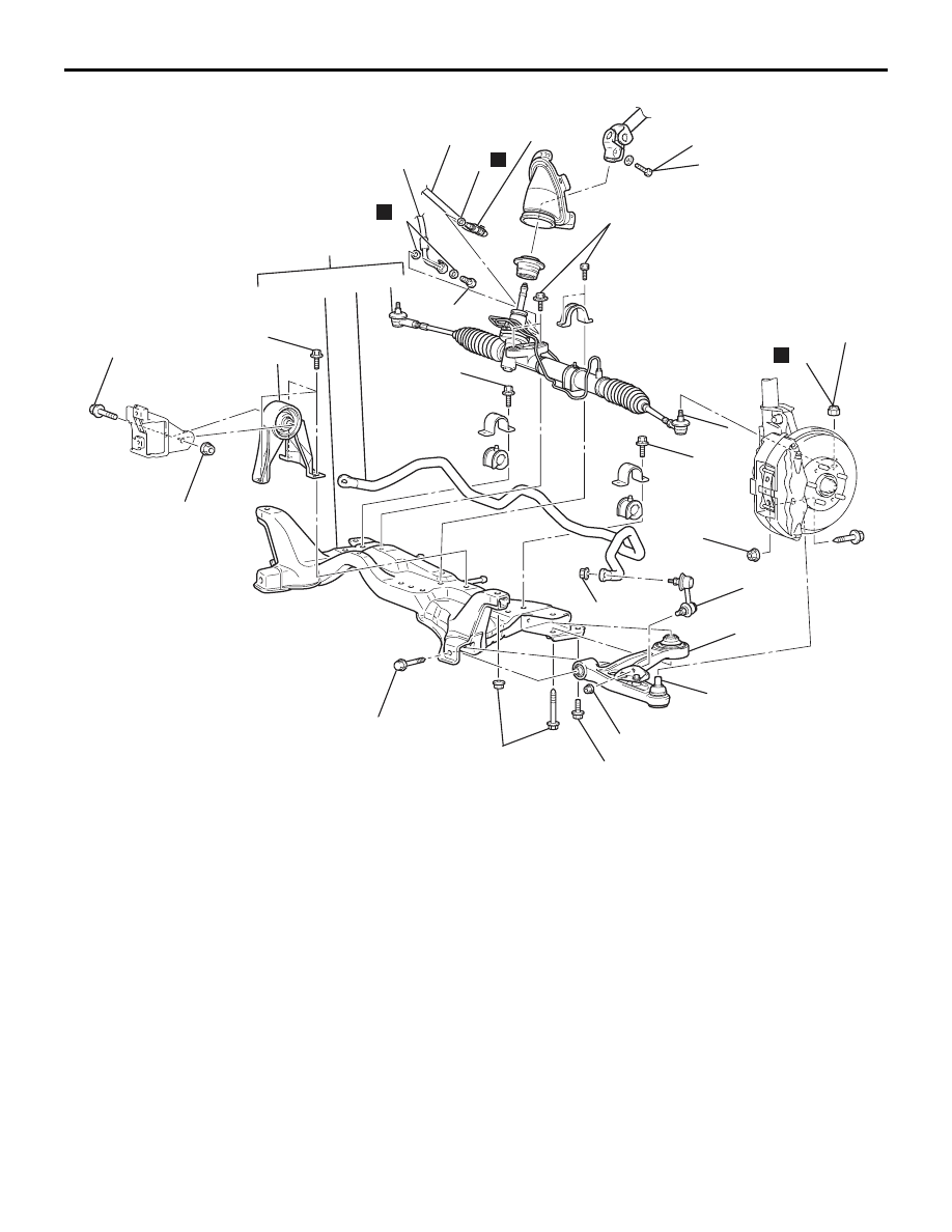
Removal steps
1.
Lower arm and knuckle
connection
2.
Stabilizer link
<<
A
>>
3.
Lower arm assembly
4.
Pressure hose connection
5.
Gaskets
6.
Return hose and return pipe
7.
O-ring
8.
Steering shaft assembly and gear
box connecting bolt
9.
Self-locking nut
<<
B
>>
10. Tie rod end and knuckle
connection
11. Engine rear roll stopper bolt
<<
C
>>
12. Front axle No.1 crossmember
assembly
13. Engine rear roll stopper bracket
>>
A
<< 14. Stabilizer bar
15. Steering gear and linkage
16. Front axle No.1 crossmember
CROSSMEMBER
POWER PLANT MOUNT
32-13
Removal steps (Continued)
CROSSMEMBER
POWER PLANT MOUNT
32-14
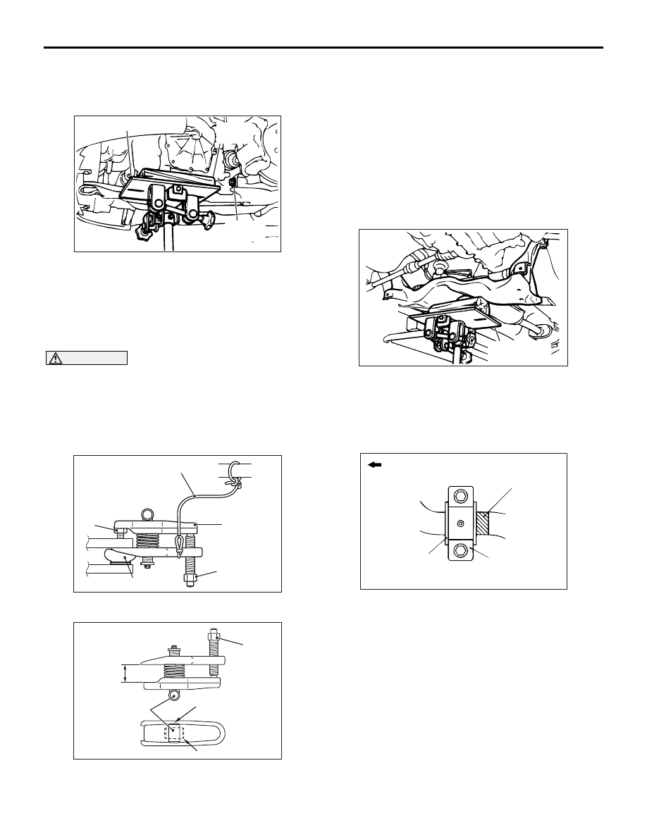
REMOVAL SERVICE POINTS
<<A>> LOWER ARM ASSEMBLY
REMOVAL
AC210537AB
Transmission jack
Mounting
bolt
Wooden
block
Lift the transmission with a transmission jack, and
then withdraw the front mounting bolt on the left
lower arm assembly.
<<B>> TIE ROD END AND KNUCKLE
DISCONNECTION
CAUTION
• Do not remove the nut from ball joint. Loosen
it and use special tool ball joint remover
(MB991897) to avoid possible damage to ball
joint threads.
•
AC208247AD
Cord
Bolt
MB991897
Self-locking
nut
Ball joint
Hang the special tool with cord to prevent it
from falling.
1. Install the special tool as shown in the figure.
AC106821
Knob
Parallel
Bolt
Correct
Wrong
AC
2. Turn the bolt and knob as necessary to make the
jaws of the special tool parallel, tighten the bolt by
hand and confirm that the jaws are still parallel.
NOTE: When adjusting the jaws in parallel, make
sure the knob is in the position shown in the fig-
ure.
3. Tighten the bolt with a wrench to disconnect the
tie rod end.
<<C>> FRONT AXLE NO.1
CROSSMEMBER ASSEMBLY REMOVAL
AC210538AB
Transmission
jack
Wooden
block
Retain the crossmember with a transmission jack,
and then remove the crossmember mounting bolt.
INSTALLATION SERVICE POINT
>>A<< STABILIZER BAR INSTALLATION
AC006141AF
Identification
colour
Fixture
Outside of
vehicle
Bushing
Align the identification colour on the left side of the
stabilizer bar with the right end of the bushing.
INSPECTION
M1321003300246
• Check the front axle No.1 crossmember for
cracks or damage.
Нет комментариевНе стесняйтесь поделиться с нами вашим ценным мнением.
Текст