Mitsubishi Lancer Evolution IX. Manual — part 665

FUEL TANK
FUEL SUPPLY
13B-5
FUEL TANK
REMOVAL AND INSTALLATION
M1135001901095
Pre-removal Operation
• Draining Fuel
• Fuel Pump Connector Disconnection (How to Reduce
Fuel Pressure). (Refer to GROUP 13A, On-vehicle Serv-
ice
).
• Centre Exhaust Pipe Removal (Refer to GROUP 15,
Exhaust Pipe and Main Muffler
• Propeller Shaft Removal (Refer to GROUP 25, Propeller
Shaft
).
Pre-installation Operation
• Propeller Shaft Installation (Refer to GROUP 25, Propeller
Shaft
).
• Centre Exhaust Pipe Installation (Refer to GROUP 15,
Exhaust Pipe and Main Muffler
• Refilling Fuel
• Checking for Fuel Leaks
AC311018 AC
1
3
4
5
6
7
8
9
10
11
12
13
14
15
16
17
18
19
20
21
22
23
24
25
26
N
N
2
6
6
27
26 ± 4 N·m
2.5 ± 0.5 N·m
2.5 ± 0.5 N·m
2.5 ± 0.5 N·m
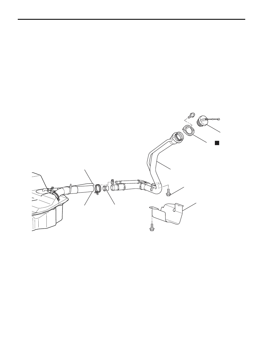
<Fuel tank assembly>
N
Fuel tank assembly removal
steps
1.
Fuel filler neck hose connection
2.
Fuel filler neck breather hose
connection
3.
Fuel vapour hose connection
4.
Fuel return hose connection
>>
B
<< 5.
Fuel high-pressure hose connection
6.
Fuel wiring harness connector
•
Parking brake cable clamp
connection (Refer to GROUP 36,
Parking Brake Cable
).
Fuel tank assembly removal
steps (Continued)
FUEL TANK
FUEL SUPPLY
13B-6
•
Rear ABS sensor connector and
harness clamp connection (Refer to
GROUP 35B, ABS Sensor
).
<<
A
>>
7.
Fuel tank assembly
8.
Fuel tank lower protector
9.
Fuel wiring harness
>>
B
<< 10. Suction hose
>>
B
<< 11. Fuel high-pressure hose
12. Fuel return hose
13. Fuel return hose
>>
B
<< 14. Fuel high-pressure hose
Fuel tank assembly removal
steps (Continued)
15. Fuel pipe assembly
16. Fuel filler neck hose
17. Fuel filler neck breather hose
18. Fuel vapour hose
19. Fuel tank check valve
20. Fuel vapour hose
<<
B
>> >>
A
<< 21. Fuel pipe and gauge assembly
22. Packing
23. Plate
<<
B
>> >>
A
<< 24. Fuel pump module
25. Packing
26. Fuel tank safety valve
27. Packing
AC310598AB
28
29
24 ± 4 N·m
30
31
32
33
34
N
<Fuel filler neck assembly>
Fuel filler neck assembly removal
steps
28. Fuel tank protector
29. Fuel filler neck hose connection
30. Fuel filler neck breather hose
connection
31. Fuel tank filler cap
32. Fuel filler neck assembly
33. Fuel filler neck valve
34. Packing
Fuel tank assembly removal
steps (Continued)
Fuel filler neck assembly removal
steps (Continued)

FUEL TANK
FUEL SUPPLY
13B-7
REMOVAL SERVICE POINTS
<<A>> FUEL TANK ASSEMBLY
REMOVAL
AC210871
Removal
direction
Tilt
AB
Floor
Differential
carrier
Fuel tank
assembly
1. Remove the differential support member and tilt
the differential carrier. (Refer to GROUP 27,
Differential Carrier
2. Hold the fuel tank assembly with a transmission
jack and remove the nuts connected to the fuel
tank assembly.
3. Remove the fuel tank assembly in the tilting
direction to avoid contact with the differential
carrier.
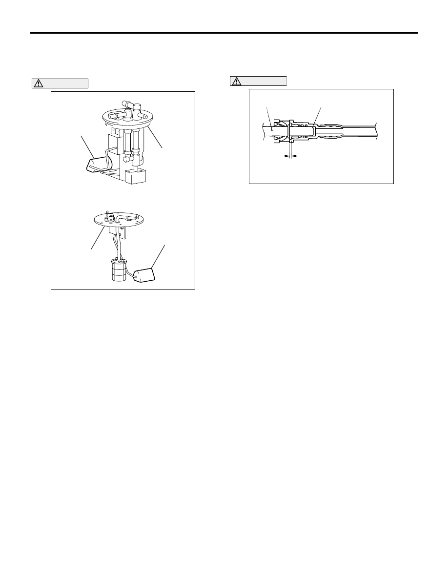
<<B>> FUEL PIPE AND GAUGE
ASSEMBLY/FUEL PUMP MODULE
REMOVAL
AC310597
Float
Fuel pump
module
AB
Float
Fuel pipe
and gauge
assembly
CAUTION
When withdrawing the fuel pipe and gauge
assembly and fuel pump module from the fuel
tank, be careful not damage the sensor unit and
the float.
FUEL TANK
FUEL SUPPLY
13B-8
INSTALLATION SERVICE POINTS
>>A<< FUEL PUMP MODULE/FUEL PIPE
AND GAUGE ASSEMBLY INSTALLATION
AC310597
Float
Fuel pump
module
AB
Float
Fuel pipe
and gauge
assembly
CAUTION
When inserting the fuel pump module and fuel
pipe and gauge assembly into the fuel tank, be
careful not damage the sensor unit and the float.
>>B<< FUEL HIGH-PRESSURE
HOSE/SUCTION HOSE INSTALLATION
AC100963
Fuel high-pressure
hose or suction hose
Corresponding
side
3.0 mm
AD
CAUTION
After connecting the quickrelease joint of the fuel
high-pressure hose or suction hose, pull the joint
lightly away from the quickrelease joint to con-
firm that it is secure. In addition, confirm that
there is a play of approximately 3.0 mm at the
joint.
Нет комментариевНе стесняйтесь поделиться с нами вашим ценным мнением.
Текст