Mitsubishi Lancer Evolution IX. Manual — part 67
AC208204
AC500094
AB
B-14
B-26
B-27
B-19
B-18
B-17
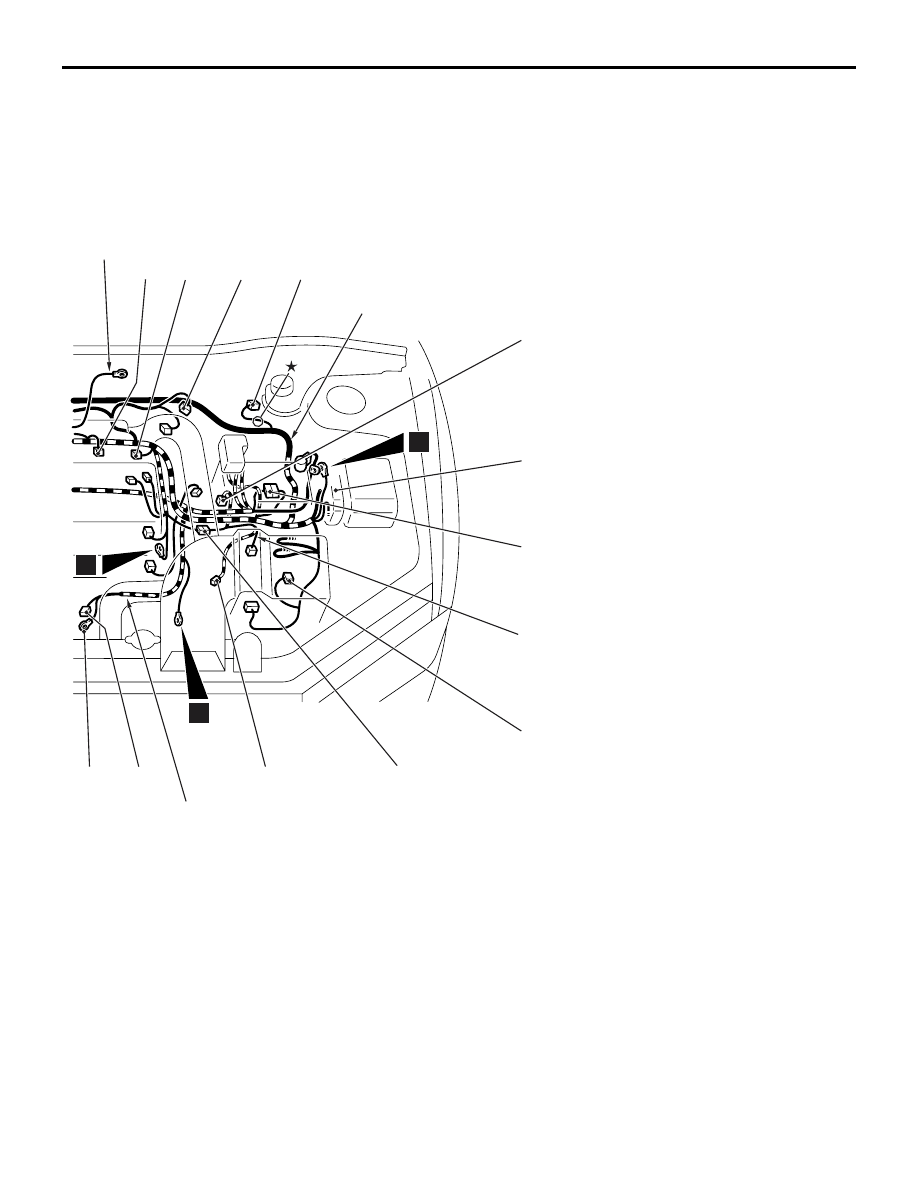
Earth cable
Control wiring
harness
Transmission
wiring harness
Battery wiring
harness
B-03
B-05
B-04
B-21
B-06X
B-12X
B-13X
4
10
11
B-30
B-18
(2-B)
Injector (3)
B-19
(1)
Starter
B-20
(2-B)
Injector (2)
B-21
(1-B)
Starter
B-22
(2-B)
Injector (1)
B-23
(1-B)
Oil pressure switch
B-24
(1)
Alternator
B-25
(4-GR)
Alternator
B-26
(2-GR)
Wastegate solenoid valve
B-27
(8-B)
Control wiring harness and
transmission wiring harness
combination
B-28
(2-B)
Fuel pressure control solenoid valve
B-29
(2-B)
Engine oil level sensor
B-30
(2-B)
Transmission oil temperature sensor
ENGINE AND TRANSMISSION
CONFIGURATION DIAGRAMS
80-9

ENGINE AND TRANSMISSION
CONFIGURATION DIAGRAMS
80-10
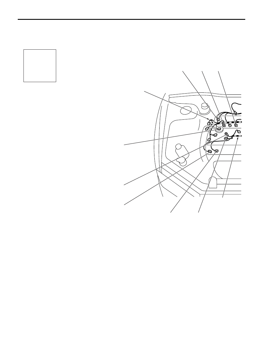
ENGINE AND TRANSMISSION <LH drive vehicles> (CONTINUED)
AC500093
AC
B-122
B-117
B-101
B-118
B-114
B-108
Connector
symbol
-101
thru
-124
B
Connector colour
code
B : Black
BR : Brown
G : Green
GR : Grey
L : Blue
None : Milk white
O : Orange
R : Red
V : Violet
Y : Yellow
B-113
B-120
B-121
B-119
B-123
B-101 (2-BR)
EGR control solenoid valve
B-103 (3-GR)
Ignition coil (1)
B-104 (6-B)
Idle speed control servo
B-105 (7-B)
Air flow sensor
B-106 (3-B)
Exhaust camshaft position sensor
B-107 (2-B)
Engine coolant temperature sensor
B-108 (2-GR)
Detonation sensor

AC208204
AC500094
AC
B-124
B-111
B-105
B-112
B-106
B-104
B-107
Earth cable
Control wiring
harness
Transmission
wiring harness
Battery wiring
harness
4
10
11
B-103
B-111 (2-B)
Back-up lamp switch
B-112 (1-B)
Engine coolant temperature gauge
unit
B-113 (4-B)
Oxygen sensor (Front)
B-114 (3-GR)
Ignition coil (2)
B-117 (3-B)
Crank angle sensor
B-118 (34-B)
ABS-ECU
B-119 (6-B)
Injector resistor
B-120 (4)
Fuel pump relay (3)
B-121 (2-B)
Fuel pump resistor
B-122 (4)
Electric pump relay
B-123 (2-B)
Oil feeder control valve
B-124 (3-B)
Intake camshaft position sensor
ENGINE AND TRANSMISSION
CONFIGURATION DIAGRAMS
80-11
ENGINE AND TRANSMISSION
CONFIGURATION DIAGRAMS
80-12
ENGINE AND TRANSMISSION <RH drive vehicles>
M1801000401701
AC500096
AB
Battery wiring
harness
B-22
B-28
B-20
B-02
B-29
B-24
B-25
Control wiring
harness
Connector
symbol
-01
thru
-29
B
Connector colour
code
B : Black
BR : Brown
G : Green
GR : Grey
L : Blue
None : Milk white
O : Orange
R : Red
V : Violet
Y : Yellow
B-23
B-01
(5-GR)
Windshield wiper motor
B-02
(2-B)
Purge control solenoid valve
B-03
(4-B)
Throttle position sensor
B-04
(3-B)
Vehicle speed sensor
B-06X (1)
Engine speed detection connector
B-10X (4)
Ignition coil relay
B-12X (4)
Engine control relay
B-13X (4)
A/C compressor relay
B-14
(10-B)
Control wiring harness and battery
wiring harness combination
B-17
(2-B)
Injector (4)
Нет комментариевНе стесняйтесь поделиться с нами вашим ценным мнением.
Текст