Mitsubishi Lancer Evolution IX. Manual — part 66
AC500088
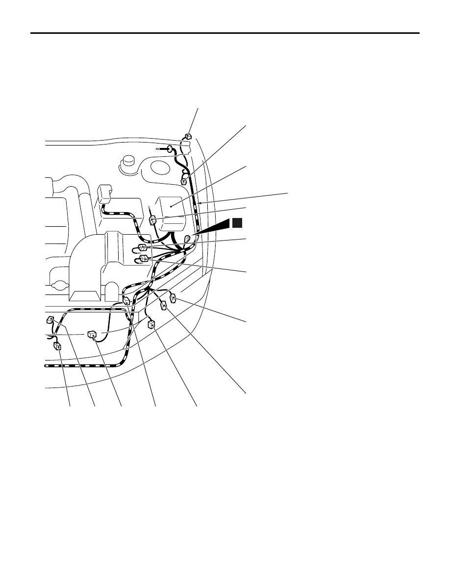
A-15
A-31
A-18
A-33
A-03
A-12
A-05X
A-06X
A-07X
A-09X
A-10X
A-11X
A-02
A-13
A-29
A-17
A-19
Front wiring
harness (LH)
AB
12
A-44
A-21
(2-B)
Headlamp (HI: RH)
A-25
(2-BR)
Dual pressure switch
A-27
(2-B)
Wheel speed sensor (Front: RH)
A-29
(8-B)
Front wiring harness (LH) and control
wiring harness combination
A-31
(8-B)
Headlamp assembly (LH)
A-33
(2-Y)
Front impact sensor (LH)
A-34
(2-B)
Condenser fan motor
A-35
(2-GR)
Condenser fan motor
A-36
(1-B)
A/C compressor
A-37
(2-Y)
Front impact sensor (RH)
A-39
(8-B)
Headlamp assembly (RH)
A-40
(1-B)
Power steering fluid pressure switch
A-44
(2-BR)
Outside thermo sensor
ENGINE COMPARTMENT
CONFIGURATION DIAGRAMS
80-5

ENGINE COMPARTMENT
CONFIGURATION DIAGRAMS
80-6
ENGINE COMPARTMENT <RH drive vehicles>
M1801000302224
AC500090
AB
1
A-34
A-35
A-37
A-40
A-36
A-21
A-39
A-01
A-43
Front wiring
harness (RH)
A-27
A-25
A-42
Connector
symbol
A
Connector colour
code
B : Black
BR : Brown
G : Green
GR : Grey
L : Blue
None : Milk white
O : Orange
R : Red
V : Violet
Y : Yellow
A-01
(2-GR)
Side turn signal lamp (RH)
A-02
(2-GR)
Side turn signal lamp (LH)
A-03
(2-B)
Wheel speed sensor (Front: LH)
A-05X (4)
Horn relay
A-06X (4)
Condenser fan relay (LO)
A-07X (4)
Condenser fan relay (HI)
A-09X (4)
Fan control relay
A-10X (11)
Front-ECU
A-11X (11)
Front-ECU
A-12
(2-B)
Front wiring harness (LH) and control
wiring harness combination
A-15
(2-B)
Headlamp (HI: LH)
A-17
(3-GR)
Fan controller
A-18
(1-B)
Horn (HI)
A-19
(1-B)
Horn (LO)
AC500091
AB
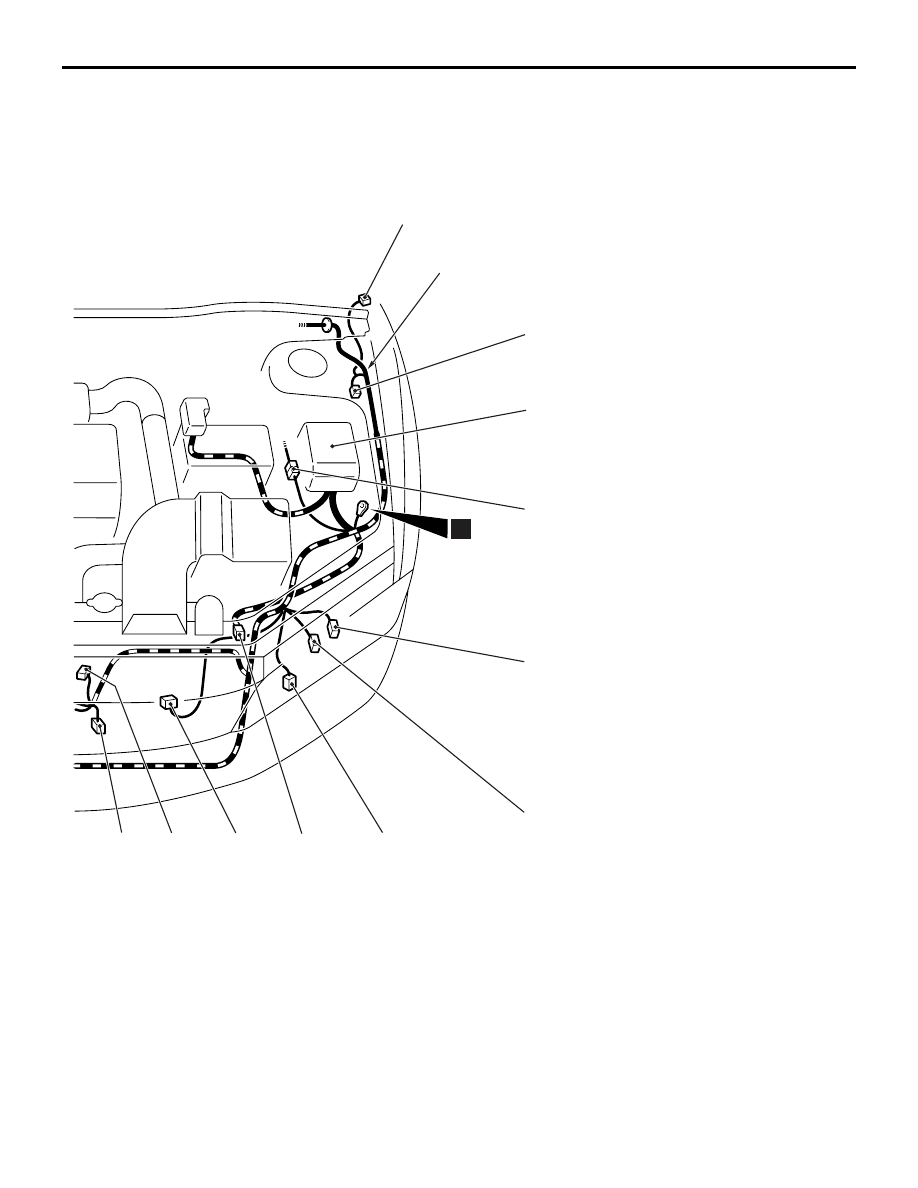
A-02
A-03
A-05X
A-06X
A-07X
A-09X
A-10X
A-11X
A-12
A-18
A-33
A-17
A-19
Front wiring
harness (LH)
A-15
A-31
12
A-44
A-21
(2-B)
Headlamp (HI: RH)
A-25
(2-BR)
Dual pressure switch
A-27
(2-B)
Wheel speed sensor (Front: RH)
A-31
(8-B)
Headlamp assembly (LH)
A-33
(2-Y)
Front impact sensor (LH)
A-34
(2-B)
Condenser fan motor
A-35
(2-GR)
Condenser fan motor
A-36
(1-B)
A/C compressor
A-37
(2-Y)
Front impact sensor (RH)
A-39
(8-B)
Headlamp assembly (RH)
A-40
(1-B)
Power steering fluid pressure switch
A-42
(2)
No connection
A-43
(2-GR)
Brake fluid level switch
A-44
(2-BR)
Outside thermo sensor
ENGINE COMPARTMENT
CONFIGURATION DIAGRAMS
80-7

ENGINE AND TRANSMISSION
CONFIGURATION DIAGRAMS
80-8
ENGINE AND TRANSMISSION
ENGINE AND TRANSMISSION <LH drive vehicles>
M1801000401693
AC500093
AB
B-28
B-25
B-01
B-24
Connector
symbol
-01
thru
-30
B
Connector colour
code
B : Black
BR : Brown
G : Green
GR : Grey
L : Blue
None : Milk white
O : Orange
R : Red
V : Violet
Y : Yellow
B-20
B-22
B-29
B-02
B-23
B-01
(5-GR)
Windshield wiper motor
B-02
(2-B)
Purge control solenoid valve
B-03
(4-B)
Throttle position sensor
B-04
(3-B)
Vehicle speed sensor
B-05
(2-GR)
Brake fluid level switch
B-06X (1)
Engine speed detection connector
B-12X (4)
Engine control relay
B-13X (4)
A/C compressor relay
B-14
(10-B)
Control wiring harness and battery
wiring harness combination
B-17
(2-B)
Injector (4)
Нет комментариевНе стесняйтесь поделиться с нами вашим ценным мнением.
Текст