Mitsubishi Lancer Evolution IX. Manual — part 65
80-1
GROUP 80
CONTENTS
OVERALL CONFIGURATION
DIAGRAM. . . . . . . . . . . . . . . . . . . . . .
OVERALL WIRING DIAGRAM
<LH drive vehicles>. . . . . . . . . . . . . . . . . . .
OVERALL WIRING DIAGRAM
<RH drive vehicles> . . . . . . . . . . . . . . . . . .
ENGINE COMPARTMENT. . . . . . . . .
ENGINE COMPARTMENT
<LH drive vehicles>. . . . . . . . . . . . . . . . . . .
ENGINE COMPARTMENT
<RH drive vehicles> . . . . . . . . . . . . . . . . . .
ENGINE AND TRANSMISSION. . . . .
ENGINE AND TRANSMISSION
<LH drive vehicles>. . . . . . . . . . . . . . . . . . .
ENGINE AND TRANSMISSION
<RH drive vehicles> . . . . . . . . . . . . . . . . . .
DASH PANEL . . . . . . . . . . . . . . . . . . .
DASH PANEL <LH drive vehicles> . . . . . . .
DASH PANEL <RH drive vehicles>. . . . . . .
FLOOR AND ROOF . . . . . . . . . . . . . .
FLOOR AND ROOF <LH drive vehicles> . .
FLOOR AND ROOF <RH drive vehicles> . .
DOOR . . . . . . . . . . . . . . . . . . . . . . . . .
DOOR <LH drive vehicles> . . . . . . . . . . . . .
DOOR <RH drive vehicles>. . . . . . . . . . . . .
TRUNK (LUGGAGE COMPARTMENT)
TRUNK <LH drive vehicles> . . . . . . . . . . . .
TRUNK <RH drive vehicles> . . . . . . . . . . . .

OVERALL CONFIGURATION DIAGRAM
CONFIGURATION DIAGRAMS
80-2
OVERALL CONFIGURATION DIAGRAM
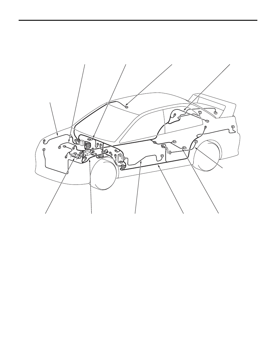
OVERALL WIRING DIAGRAM <LH drive vehicles>
M1801000101175
AC208864 AE
Control wiring
harness
Front wiring
harness (RH)
Instrument panel
wiring harness
Roof wiring
harness
Floor wiring
harness (RH)
Battery wiring
harness
Front wiring
harness (LH)
Front door
wiring harness*
Floor wiring
harness (LH)
Fuel wiring
harness
Rear door
wiring harness*
NOTE:
.
1. This illustration shows only major wiring harnesses.
2. *: also equipped at the right side.
OVERALL CONFIGURATION DIAGRAM
CONFIGURATION DIAGRAMS
80-3
OVERALL WIRING DIAGRAM <RH drive vehicles>
M1801000101186
AC212063
AC310155AB
Control wiring
harness
Front wiring
harness (RH)
Instrument panel
wiring harness
Roof wiring
harness
Floor wiring
harness (RH)
Battery wiring
harness
Front wiring
harness (LH)
Front door
wiring harness*
Floor wiring
harness (LH)
Fuel wiring
harness
Rear door
wiring harness*
NOTE:
.
1. This illustration shows only major wiring harnesses.
2. *: also equipped at the right side.

ENGINE COMPARTMENT
CONFIGURATION DIAGRAMS
80-4
ENGINE COMPARTMENT
ENGINE COMPARTMENT <LH drive vehicles>
M1801000302213
AC500087
AB
Connector
symbol
A
A-01
A-25
A-40
A-27
A-36
A-34
A-35
A-21
A-37
A-39
Front wiring
harness (RH)
1
Connector colour
code
B : Black
BR : Brown
G : Green
GR : Grey
L : Blue
None : Milk white
O : Orange
R : Red
V : Violet
Y : Yellow
A-01
(2-GR)
Side turn signal lamp (RH)
A-02
(2-GR)
Side turn signal lamp (LH)
A-03
(2-B)
Wheel speed sensor (Front: LH)
A-05X (4)
Horn relay
A-06X (4)
Condenser fan relay (LO)
A-07X (4)
Condenser fan relay (HI)
A-09X (4)
Fan control relay
A-10X (11)
Front-ECU
A-11X (11)
Front-ECU
A-12
(2-B)
Front wiring harness (LH) and control
wiring harness combination
A-13
(8-B)
Front wiring harness (LH) and control
wiring harness combination
A-15
(2-B)
Headlamp (HI: LH)
A-17
(3-GR)
Fan controller
A-18
(1-B)
Horn (HI)
A-19
(1-B)
Horn (LO)
Нет комментариевНе стесняйтесь поделиться с нами вашим ценным мнением.
Текст