Mitsubishi Lancer Evolution IX. Manual — part 240

SYMPTOM PROCEDURES
SMART WIRING SYSTEM (SWS) USING SWS MONITOR
54C-219
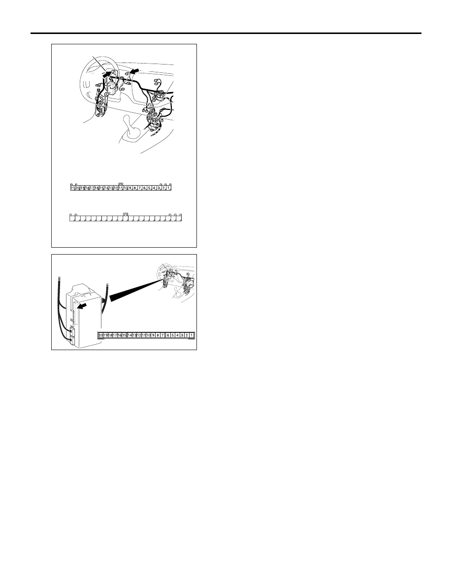
Step 4. Check the wiring harness from A-39
<front RH> or A-31 <front LH> headlamp
assembly connector terminal No.7, A-01 <side
RH> or A-02 <side LH> side turn-signal lamp
connector terminal No.1, F-08 <rear RH> or F-14
<rear LH> rear combination lamp connector
terminal No.5, or C-02 <turn-signal indicator
lamp> combination meter connector terminal
No.48 to body earth.
• Check the earth wires for open circuit.
Q: Is the check result normal?
YES :
The trouble can be an intermittent
malfunction (Refer to GROUP 00
− How to
Cope with Intermittent Malfunction
NO :
Repair the wiring harness.
AC310432
Connectors: A-01, A-39
<LHD>
A-39
A-01 (GR)
Harness side
A-01
Harness side
A-39
AB
AC310543
Connectors: A-02, A-31
<LHD>
A-31
A-02 (GR)
Harness side
A-02
Harness side
A-31
AB
AC310468
Connectors: F-08, F-14
<LHD>
F-14
F-08
Harness side
F-08
Harness side
F-14
AC
AC310446
Connector: C-02
<LHD>
AK
Harness side
31
35
36
37
38
39
40
41
45
46
47
48
49
50
51
34
44
33
43
32
42
C-02 (L)

SYMPTOM PROCEDURES
SMART WIRING SYSTEM (SWS) USING SWS MONITOR
54C-220
Step 5. Connector check: C-226 ETACS-ECU
connector
Q: Is the check result normal?
YES :
Go to Step 6.
NO :
Repair the defective connector.
Step 6. Check the wiring harness from the A-39
<front RH> or A-31 <front LH> headlamp
assembly connector terminal No.2, the A-01
<side RH> or A-02 <side LH> side turn-signal
lamp connector terminal No.2, the F-08 <rear RH>
or F-14 <rear LH> rear combination lamp
connector terminal No.1, the C-02 <turn-signal
indicator lamp RH> combination meter connector
terminal No.49 or C-01 <turn-signal indicator
lamp LH> combination lamp connector terminal
No.3 to C-226 ETACS-ECU connector terminal
No.9 <RH> or 14 <LH>.
AC310450
Connector: C-226
AB
Junction block side
Junction block (rear view)
<LHD>
AC310432
Connectors: A-01, A-39
<LHD>
A-39
A-01 (GR)
Harness side
A-01
Harness side
A-39
AB
AC310543
Connectors: A-02, A-31
<LHD>
A-31
A-02 (GR)
Harness side
A-02
Harness side
A-31
AB
AC310468
Connectors: F-08, F-14
<LHD>
F-14
F-08
Harness side
F-08
Harness side
F-14
AC
SYMPTOM PROCEDURES
SMART WIRING SYSTEM (SWS) USING SWS MONITOR
54C-221
AC310447
Connectors: C-01, C-02
AE
<LHD>
C-01
Harness side
C-02
Harness side
31
32
33
34
35
36
37
38
39
40
41
42
43
44
45
46
47
48
49
50
51
C-01
C-02(L)
AC310450
Connector: C-226
AB
Junction block side
Junction block (rear view)
<LHD>

SYMPTOM PROCEDURES
SMART WIRING SYSTEM (SWS) USING SWS MONITOR
54C-222
NOTE:
Prior to the wiring harness inspection, check interme-
diate connector C-129 <front or side LH>, C-113
<rear RH> or C-111 <side RH> and junction block
connector C-210 <front LH, side or rear RH>, C-217
<rear LH> or C-214 <front RH or turn-signal indicator
lamp>, and repair if necessary.
• Check the output lines for open circuit.
Q: Is the check result normal?
YES :
Go to Step 7.
NO :
Repair the wiring harness.
Step 7. Retest the system.
Check that the turn-signal lamps and the indicator
lamps illuminate normally.
Q: Is the check result normal?
The lamps illuminate normally at both high and low
beams. :
The trouble can be an intermittent
malfunction (Refer to GROUP 00
− How to
Cope with Intermittent Malfunction
The front turn-signal lamps do not illuminate. :
Replace the socket.
The side turn-signal lamps do not illuminate. :
Replace the socket.
The rear turn-signal lamps do not illuminate. :
Replace the socket assembly.
The turn-signal indicator lamps do not illuminate. :
Replace the combination meter.
AC310453
C-111
C-113
Connectors: C-111, C-113
AB
C-113
<LHD>
C-111
Harness side
Harness side
AC310446
C-129
Connectors: C-129
AP
<LHD>
AC310449
C-214
Harness side
21
7
16 15
17
18
20 19
1
2
3
4
5
6
23 22
24
25
28
26
27
9
8
10
11
14
12
13
Connectors: C-210, C-214, C-217
AE
C-214
Junction block (front view)
<LHD>
C-210
C-210
Harness side
10
1
6
14
5
12
13
4
11
7
2
3
8
9
C-217
C-217
Harness side
Нет комментариевНе стесняйтесь поделиться с нами вашим ценным мнением.
Текст