Mitsubishi Lancer Evolution IX. Manual — part 238

SYMPTOM PROCEDURES
SMART WIRING SYSTEM (SWS) USING SWS MONITOR
54C-211
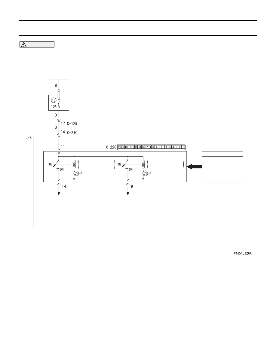
Step 4. Check the wiring harness between C-226
ETACS-ECU connector terminal No.11 and the
battery.
NOTE:
Prior to the wiring harness inspection, check interme-
diate connector C-129 and junction block connector
C-210, and repair if necessary.
• Check the power supply line for open circuit.
Q: Is the check result normal?
YES :
The trouble can be an intermittent
malfunction (Refer to GROUP 00
− How to
Cope with Intermittent Malfunction
NO :
Repair the wiring harness.
AC310450
Connector: C-226
AB
Junction block side
Junction block (rear view)
<LHD>
AC310461
Junction block (rear view)
Connector: C-226
AB
<RHD>
Junction block side
AC310446
Connector: C-129
<LHD>
AI
AC310454
Connector: C-129
<RHD>
AJ
AC310448
Junction block (front view)
Connector: C-210
AK
<LHD>
Harness side
10
1
6
14
5
12
13
4
11
7
2
3
8
9
AC310458
Junction block (front view)
Connector: C-210
AH
<RHD>
Harness side
10
1
6
14
5
12
13
4
11
7
2
3
8
9

SYMPTOM PROCEDURES
SMART WIRING SYSTEM (SWS) USING SWS MONITOR
54C-212
Step 5. Retest the system.
Check that the turn-signal lamps illuminate normally.
Q: Is the check result normal?
YES :
The trouble can be an intermittent
malfunction (Refer to GROUP 00
− How to
Cope with Intermittent Malfunction
NO :
Replace the ETACS-ECU.
Step 6. Function diagnosis by using the SWS
monitor.
Check the SWS communication signal, which are
related to the right turn-signal lamps.
<Selected item> TURN SIGNAL - TURN-SIG. RH
• Turn-signal lamp switch: RH
• Ignition switch: ON
OK: Normal conditions displayed for all the
items
Q: Is the check result normal?
Normal conditions are displayed for all the items. :
Go to Step 7.
Normal condition is not displayed for item 10 or 11.
:
Refer to Inspection Procedure L-4 "The
column switch (lighting and turn-signal lamp
switch) signal is not received
Normal condition is not displayed for item No.30. :
Refer to Inspection Procedure L-2 "The
ignition switch (IG1) signal is not received
."
Step 7. Function diagnosis by using the SWS
monitor.
Check the SWS communication signal, which are
related to the left turn-signal lamps.
<Selected item> TURN SIGNAL - TURN-SIG. LH
• Turn-signal lamp switch: LH
• Ignition switch: ON
OK: Normal condition is displayed.
Q: Is the check result normal?
Normal conditions are displayed for all the items. :
Go to Step 8.
Normal condition is not displayed for item 10 or 11.
:
Refer to Inspection Procedure L-4 "The
column switch (lighting and turn-signal lamp
switch) signal is not received
Step 8. Retest the system.
Check that the turn-signal lamps illuminate.
Q: Is the check result normal?
YES :
The trouble can be an intermittent
malfunction (Refer to GROUP 00
− How to
Cope with Intermittent Malfunction
NO :
Replace the ETACS-ECU.
Item No.
Item name
Normal condition
Item 10
TURN SIG.RH
ON
Item 11
TURN SIG.LH
OFF
Item 30
IG SW(IG1)
ON
Item No.
Item name
Normal condition
Item 10
TURN SIG.RH
OFF
Item 11
TURN SIG.LH
ON
SYMPTOM PROCEDURES
SMART WIRING SYSTEM (SWS) USING SWS MONITOR
54C-213
INSPECTION PROCEDURE I-2: The hazard warning lamps do not illuminate.
CAUTION
Whenever the ECU is replaced, ensure that the
input and output signal circuits are normal.
COMMENTS ON TROUBLE SYMPTOM
If the hazard warning lamps do not illuminate, the
hazard warning lamp input signal circuit or the
ETACS-ECU may be defective.
POSSIBLE CAUSES
• Malfunction of the hazard warning lamp switch
• Malfunction of the ETACS-ECU
• Damaged harness wires and connectors
Wire colour code
B : Black LG : Light green G : Green L : Blue W : White Y : Yellow SB : Sky blue
BR : Brown O : Orange GR : Gray R : Red P : Pink V : Violet
BATTERY
· COMBINATION METER
ETACS-ECU
HAZARD
WARNING
LAMP SWITCH
RELAY
BOX
TURN-SIGNAL
LAMP RELAY: LH
TURN-SIGNAL
LAMP RELAY: RH
INPUT SIGNAL
· HEADLAMP
ASSEMBLY (LH)
· SIDE TURN SIGNAL
LAMP (LH)
· REAR COMBINATION
LAMP (LH)
· COMBINATION METER
· HEADLAMP
ASSEMBLY (RH)
· SIDE TURN SIGNAL
LAMP (RH)
· REAR COMBINATION
LAMP (RH)
J/B SIDE
Hazard Warning Lamp Circuit
SYMPTOM PROCEDURES
SMART WIRING SYSTEM (SWS) USING SWS MONITOR
54C-214
DIAGNOSIS PROCEDURE
Step 1. Check that the turn-signal lamps operate.
Check that the turn-signal lamps illuminate normally.
Q: Is the check result normal?
YES :
Go to Step 2.
NO :
Refer to Inspection Procedure I-1 "The turn
signal lamps do not illuminate
Step 2. Pulse check
Check the input signal from the hazard warning lamp
switch.
OK: The M.U.T.-II/III sounds or the voltmeter
needle fluctuates.
Q: Is the check result normal?
YES :
Go to Step 3.
NO :
Refer to Inspection Procedure L-10 "The
hazard warning lamp switch signal is not
received
."
Step 3. Retest the system.
Check that the hazard warning lamps illuminate.
Q: Is the check result normal?
YES :
The trouble can be an intermittent
malfunction (Refer to GROUP 00
− How to
Cope with Intermittent Malfunction
NO :
Replace the ETACS-ECU.
System switch
Check condition
Hazard warning
lamp switch
When the hazard warning lamp
switch is turned from off to on
Нет комментариевНе стесняйтесь поделиться с нами вашим ценным мнением.
Текст