Mitsubishi Lancer Evolution IX. Manual — part 239

SYMPTOM PROCEDURES
SMART WIRING SYSTEM (SWS) USING SWS MONITOR
54C-215
INSPECTION PROCEDURE I-3: Any of the turn-signal lamps does not illuminate. <LH drive vehicles>
CAUTION
Whenever the ECU is replaced, ensure that the
input and output signal circuits are normal.
COMMENTS ON TROUBLE SYMPTOM
If any of the turn-signal lamps does not illuminate
normally, wiring harness connector(s) or the bulb
may be defective.
POSSIBLE CAUSES
• Defective turn-signal lamp bulb
• Damaged harness wires and connectors
SIDE
TURN
SIGNAL
LAMP
(LH)
TURN-SIGNAL
LAMP RELAY: LH
HEADLAMP
ASSEMBLY
(LH)
HEADLAMP
ASSEMBLY
(RH)
REAR
COMBINATION
LAMP (RH)
REAR
COMBINATION
LAMP (LH)
SIDE TURN
SIGNAL LAMP
(RH)
COMBINATION
METER
J/B SIDE
ETACS-ECU
TURN-SIGNAL
LAMP RELAY: RH
Turn-Signal Lamps Circuit <LHD>
Wire colour code
B : Black LG : Light green G : Green L : Blue W : White Y : Yellow SB : Sky blue
BR : Brown O : Orange GR : Grey R : Red P : Pink V : Violet PU : Purple
SYMPTOM PROCEDURES
SMART WIRING SYSTEM (SWS) USING SWS MONITOR
54C-216
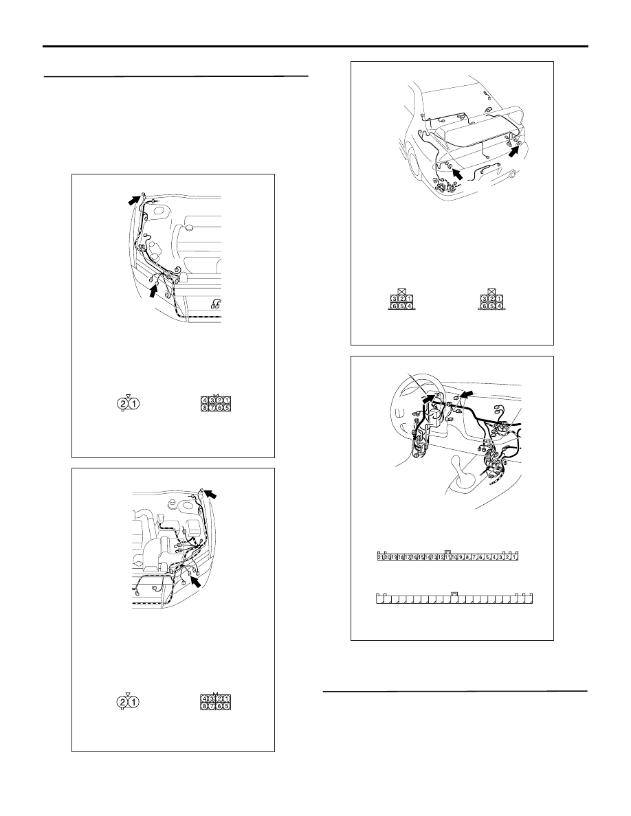
DIAGNOSTIC PROCEDURE
Step 1. Connector check: A-39 <front RH> or
A-31 <front LH> headlamp assembly connector,
A-01 <side RH> or A-02 <side LH> side
turn-signal lamp connector, F-08 <rear RH> or
F-14 <rear LH> rear combination lamp connector,
C-02 <turn-signal indicator lamp> and C-01
<turn-signal indicator lamp (LH)> combination
meter connector
Q: Is the check result normal?
YES :
Go to Step 2.
NO :
Repair the defective connector.
Step 2. Check the bulb(s) of the turn-signal lamps
or the turn-signal indicator lamps.
Check the bulb(s) of the defective lamp.
Q: Is the check result normal?
YES :
Go to Step 3.
NO :
Replace the bulb(s) of the defective lamp.
AC310432
Connectors: A-01, A-39
<LHD>
A-39
A-01 (GR)
Harness side
A-01
Harness side
A-39
AB
AC310543
Connectors: A-02, A-31
<LHD>
A-31
A-02 (GR)
Harness side
A-02
Harness side
A-31
AB
AC310468
Connectors: F-08, F-14
<LHD>
F-14
F-08
Harness side
F-08
Harness side
F-14
AC
AC310447
Connectors: C-01, C-02
AE
<LHD>
C-01
Harness side
C-02
Harness side
31
32
33
34
35
36
37
38
39
40
41
42
43
44
45
46
47
48
49
50
51
C-01
C-02(L)

SYMPTOM PROCEDURES
SMART WIRING SYSTEM (SWS) USING SWS MONITOR
54C-217
Step 3. Resistance measurement at the A-39
<front RH> or A-31 <front LH> headlamp
assembly connector, the A-01 <side RH> or A-02
<side LH> side turn-signal lamp connector, the
F-08 <rear RH> or F-14 <rear LH> rear
combination lamp connector, the C-02
<turn-signal indicator lamp> combination meter
connector
(1) Disconnect the connector, and measure at the
wiring harness side.
AC310432
Connectors: A-01, A-39
<LHD>
A-39
A-01 (GR)
Harness side
A-01
Harness side
A-39
AB
AC310543
Connectors: A-02, A-31
<LHD>
A-31
A-02 (GR)
Harness side
A-02
Harness side
A-31
AB
AC310468
Connectors: F-08, F-14
<LHD>
F-14
F-08
Harness side
F-08
Harness side
F-14
AC
AC310446
Connector: C-02
<LHD>
AK
Harness side
31
35
36
37
38
39
40
41
45
46
47
48
49
50
51
34
44
33
43
32
42
C-02 (L)

SYMPTOM PROCEDURES
SMART WIRING SYSTEM (SWS) USING SWS MONITOR
54C-218
(2) Measure the resistance between the defective
lamp connector terminal and body earth.
•
Resistance between A-39 <front RH> headlamp
assembly connector terminal No.7 and body
earth
• Resistance between A-31 <front LH> head-
lamp assembly connector terminal No.7 and
body earth
•
Resistance between A-01 <side RH> side
turn-signal lamp connector terminal No.1 and
body earth
• Resistance between A-02 <side LH> side
turn-signal lamp connector terminal No.1 and
body earth
•
Resistance between F-08 <rear RH> rear combi-
nation lamp connector terminal No.5 and
body earth
• Resistance between F-14 <rear LH> rear
combination lamp connector terminal No.5
and body earth
•
Resistance between C-02 <turn-signal indicator
lamp> combination meter terminal No.48 and
body earth
OK: 2
Ω or less
Q: Is the check result normal?
YES :
Go to Step 5.
NO :
Go to Step 4.
AC301541HG
Connector A-31, A-39
(Harness side)
AC301541HH
Connector A-01, A-02
(Harness side)
AC301541HI
Connector F-08, F-14
(Harness side)
AC301541HE
Connector C-02
(Harness side)
31
35
36
37
38
39
40
41
45
46
47
48
49
50
51
34
44
33
43
32
42
Нет комментариевНе стесняйтесь поделиться с нами вашим ценным мнением.
Текст