Mitsubishi Montero (1991+). Manual — part 55

oil seal using seal driver. Apply grease to outside circumference of
bearing outer race. Apply grease to lip of oil seal and to roller
surfaces of bearing inner race.
2) Press bearing onto axle shaft. Install rear brake assembly
and bearing case. Pack bearing case and axle threads with grease.
Install lock washer (tab aligned with axle slot) and lock nut (chamfer
toward lock washer). Tighten lock nut to 130-159 ft. lbs. (176-216 N.
m).
3) Bend tabs on lock washer into slots of lock nut. Apply
grease to oil seal area of rear axle housing. Adjust clearance between
bearing case and rear axle by inserting .04" (1.0 mm) shim and "O"
ring into left rear axle housing.
4) Apply semi-drying sealant to mating surface of bearing
case. Install left axle shaft into rear housing. Tighten nuts
diagonally to 36-43 ft. lbs. (49-58 N.m).
5) Install right axle shaft without shims and "O" ring.
Temporarily tighten to about 53 INCH lbs. (6 N.m). Using a feeler
gauge, measure clearance between bearing case and rear axle housing.
6) Remove right axle shaft. Install shims to equal bearing
case-to-axle housing clearance plus .002-.008" (.05-.20 mm). Install
"O" ring to right rear axle housing. Apply sealant to mating surfaces
of bearing case and shim. See Fig. 10.
7) Install axle into housing, tightening nuts diagonally to
36-43 ft. lbs. (50-58 N.m). Check axle shaft for .002-.008" (.05-.20
mm) end play using dial indicator.
Fig. 10: Applying Sealant (Montero, Pickup & Ram-50)
Courtesy of Mitsubishi Motor Sales of America.
Removal (Pickup & Ram-50)
1) With drum removed, disconnect brake line from wheel
cylinder. Disconnect parking brake cable end, and remove cable
attaching bolts. Remove brake backing plate, bearing case and axle
shaft as an assembly. If axle shaft binds, use slide hammer with
puller to remove.
2) Remove shims, "O" ring and snap ring. Retain shims for
reassembly. Secure axle shaft assembly in a vise, and remove one
retainer bolt from backing plate. Push bearing case completely to side
of dust cover. Place adhesive tape around edge of bearing case at
retainer bolt hole to prevent damage.
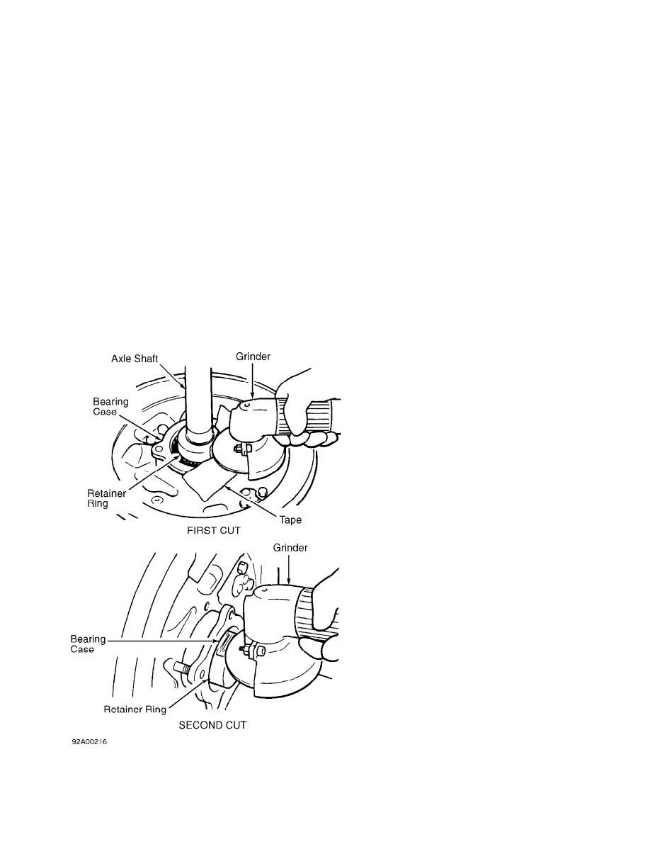
3) Secure axle shaft, and grind retainer ring until retainer
ring wall thickness is .04-.06" (1.0-1.5 mm) on axle shaft side and
retainer ring wall thickness is .08" (2.0 mm) on bearing side. See
Fig. 11.
CAUTION: DO NOT damage bearing case or axle shaft when grinding or
chiseling retainer ring.
4) Change angle of grind, and remove remaining .08" (2.0 mm)
of retainer ring wall on bearing side. See Fig. 11. Using a chisel,
cut retainer ring, and remove. DO NOT damage axle shaft.
Fig. 11: Grinding Bearing Retainer Ring (Pickup & Ram-50)
Courtesy of Mitsubishi Motor Sales of America.
5) Install Puller (MB990787-01) to remove bearing case from
axle shaft. Rotate nuts with equal force to remove wheel bearing.
Remove bearing outer race using a hammer and drift. Remove oil seal
from axle housing using a slide hammer and hook.
Installation
1) Apply Multipurpose Grease (SAE J310) to oil seal. Install
oil seal using seal driver. Apply grease to outside circumference of
oil seal lip. Install backing plate and bearing case. Apply grease to
oil seal.
2) Press new oil seal into bearing case until it is flush
with face of bearing case. Apply grease to lip of oil seal and to
external surfaces of bearing outer race. Press bearing outer race into
bearing case.
3) Apply grease to roller surfaces of bearing inner race.
Install rear brake assembly and bearing case. Pack bearing case and
axle threads with grease. Install new retainer ring.
4) Adjust clearance between bearing case and rear axle by
inserting .04" (1.0 mm) shim and "O" ring into left rear axle housing.
Apply semi-drying sealant to mating surface of bearing case. Install
left axle shaft into rear housing. Tighten nuts diagonally to 36-43
ft. lbs. (50-58 N.m).
5) Install right axle shaft without shims and "O" ring.
Temporarily tighten to about 53 INCH lbs. (6 N.m). Using a feeler
gauge, measure clearance between bearing case and rear axle housing.
6) Remove right axle shaft. Install shims to equal bearing
case-to-axle housing clearance plus .002-.008" (.05-.20 mm). Install
"O" ring to right rear axle housing. Apply sealant to mating surface
of bearing case. See Fig. 10.
7) Install axle into housing, tightening nuts diagonally to
36-43 ft. lbs. (49-58 N.m). Check axle shaft for .002-.008" (.05-.20
mm) end play using dial indicator.
OVERHAUL
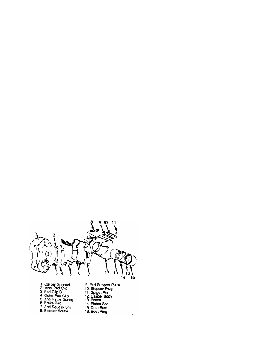
NOTE: For exploded views of front disc brake caliper, see Fig. 12.
For exploded view of master cylinder, see Fig. 13.
Fig. 12: Exploded View of Front Disc Brake Caliper (Typical)
Courtesy of Mitsubishi Motor Sales of America.
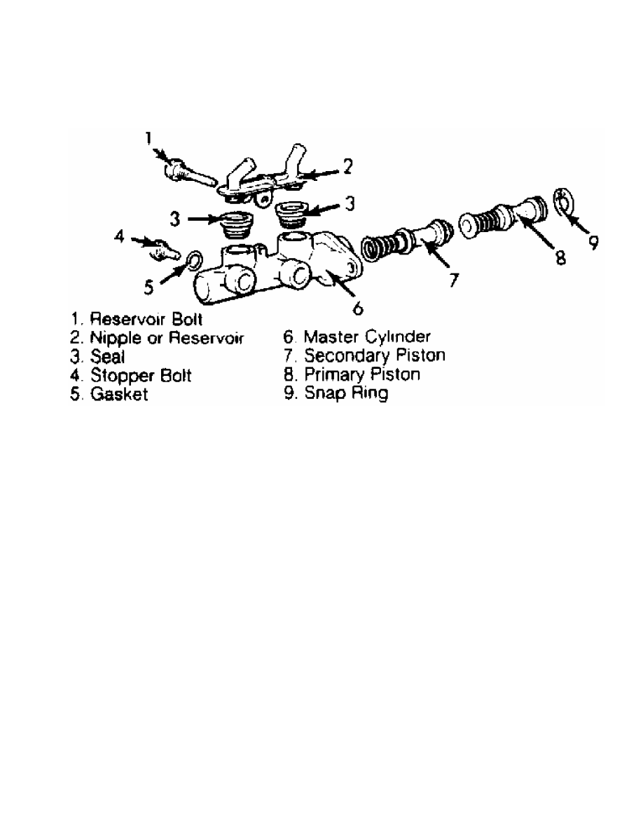
Fig. 13: Exploded View of Master Cylinder (Typical)
Courtesy of Mitsubishi Motor Sales of America.
DISC BRAKE SPECIFICATIONS
DISC BRAKE SPECIFICATIONS TABLE
Application In. (mm)
Disc Diameter
Montero
2.6L . . . . . . . . . .. 10.2 (259)
3.0L . . . . . . . . . .. 10.9 (277)
Pickup & Ram-50
2WD . . . . . . . . . ... 10.2 (259)
4WD . . . . . . . . . ... 10.9 (277)
Lateral Runout . . . . . . . . .006 (.15)
Parallelism . . . . . . . . . . .. ( 1)
Original Thickness . . . . . . . .. .87 (22)
Master Cylinder Diameter . . . . . .938 (23.83)
Minimum Refinish Thickness . . . . . .80 (20.4)
Discard Thickness . . . . . . . . .78 (19.8)
(1) - Information is not available.
DRUM BRAKE SPECIFICATIONS
DRUM BRAKE SPECIFICATIONS TABLE
Application In. (mm)
Drum Diameter . . . . . . . . . 10.0 (254)
Drum Width . . . . . . . . . . ... ( 1)
Master Cylinder Diameter . . . . . .938 (23.83)
Нет комментариевНе стесняйтесь поделиться с нами вашим ценным мнением.
Текст