Mitsubishi Montero (1991+). Manual — part 54
Inlet Pressure Outlet Pressure
Application psi (kg/cm
) psi (kg/cm
)
2.6L
Test 1 . . . 853 (59) . . . 473-526 (33-37)
Test 2 . . ... 1280 (88) . . . 672-757 (46-52)
3.0L
2-Door Model
Test 1 . . .. 853 (59) . . . 473-526 (33-37)
Test 2 . . . 1565 (108) . . 768-865 (54-60)
4-Door Model
Test 1 . . .. 597 (41) . . . 569-626 (39-43)
Test 2 . . . 1377 (95) . . . 843-928 (58-64)
(1) - Maximum side-to-side pressure differential
is 57 psi (4kg/cm
).
REMOVAL & INSTALLATION
FRONT BRAKE PADS
CAUTION: DO NOT remove or contaminate special grease coating on lock
pins.
Removal
1) Raise and support vehicle. Remove front wheel(s). Remove
lower lock pin or sleeve bolt. See Fig. 6. Lift caliper body upward.
2) Support caliper using wire. Remove shim(s), shim holder
(if equipped), anti-squeak shim and pad assembly from support
mounting. Remove pad clips.
Installation
If installing new pads, compress piston to bottom of bore.
Install retaining clips, pad assembly, shim(s), shim holder (if
equipped) and anti-squeak shim onto support mounting.
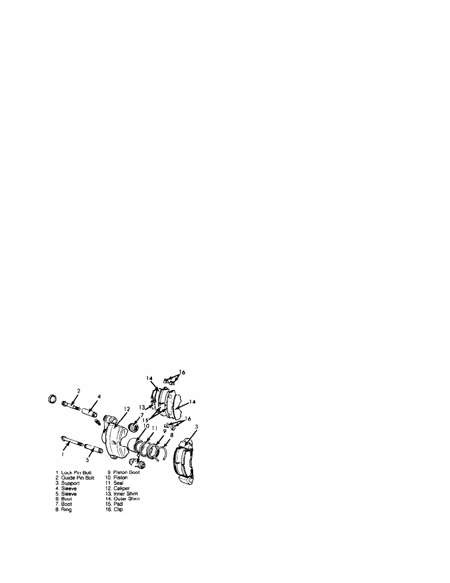
Fig. 6: Exploded View of Front Disc Brake Assembly (Typical)
Courtesy of Chrysler Motors.
FRONT BRAKE CALIPER
Removal
1) Raise and support vehicle. Remove front wheel(s). Separate
rubber flex hose from hydraulic line at brake hose mount, located on
strut housing. Secure end of hydraulic line to prevent spillage of
brake fluid.
2) Remove hose clip from brake hose mount. Disconnect brake
hose from caliper. Remove upper and lower caliper-to-steering knuckle
bolts. Lift caliper body upward. Remove caliper.
Installation
To install, reverse removal procedure. Tighten bolts to
specification. See the TORQUE SPECIFICATIONS table. Bleed brake
system. See BLEEDING BRAKE SYSTEM.
FRONT BRAKE ROTOR
Removal (Montero, Pickup 4WD & Ram-50 4WD)
Raise and support vehicle. Remove and support brake calipers.
Place hub in free-wheeling position. Remove drive hub cover using an
oil filter wrench and protective cloth. Remove snap ring, shim and
free-wheeling hub from drive axle. See Fig. 7. Remove lock washer.
Remove lock nut using Lock Nut Wrench (MB990954). Remove front hub
assembly.
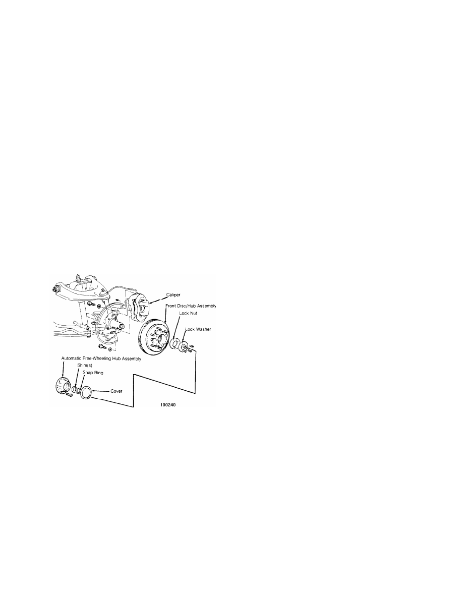
Fig. 7: Exploded View of Front Brake Assembly (4WD)
Courtesy of Mitsubishi Motor Sales of America.
Installation
1) Install front hub assembly. Install and tighten lock nut
to 94-145 ft. lbs. (127-197 N.m), and then loosen and retighten to 18
ft. lbs. (24 N.m). Loosen lock nut 30-40 degrees. Reverse removal
procedure for remaining components. After installation is complete,
check drive axle end play. Adjust end play if not .002" (.05 mm) or
less. Rotate drive axle forward and rearward until maximum end play is
obtained.
2) If adjusting axle shaft end play, use proper shim to
obtain desired end play. Shim is located behind snap ring on end of
drive axle. Install shim, and recheck axle end play.
Removal (Pickup 2WD & Ram-50 2WD)
Raise and support vehicle. Remove front caliper. Remove hub
(dust) cap, cotter pin and nut. Remove washer and outer wheel bearing.
Remove front hub assembly. Remove bolts attaching rotor to front hub,
and separate assemblies.

Installation
To install, reverse removal procedure. Tighten wheel bearings
to 22 ft. lbs. (30 N.m). Loosen nut, and then retighten to 72 INCH
lbs. (8 N.m). Install cotter pin. If pin does not align, loosen nut up
to a maximum of 30 degrees.
REAR BRAKE DRUM & SHOES
Removal
1) Raise and support vehicle. Remove wheel and brake drum.
Remove shoe return spring and brake shoe adjuster. See Fig. 8. Remove
adjusting spring, shoe retaining spring and shoe hold-down pins.
2) Remove shoe and lining assembly with parking brake lever.
Remove cable from parking lever. Remove parking brake lever snap ring,
and disengage lever from brake shoe.
Fig. 8: Exploded View of Rear Brake Assembly
Courtesy of Mitsubishi Motor Sales of America.
Installation
1) To install, reverse removal procedure. Apply Lubriplate to
backing plate bosses, adjuster assembly threads and parking brake
lever pin.
2) Set adjustment assembly so brake shoes lightly contact
brake drum. Depress brake pedal to center shoes, and check pedal
travel. Rotate brake drum to ensure free movement.
WHEEL CYLINDERS
Removal & Installation
Raise and support vehicle. Remove rear brake drum and shoes.
See REAR BRAKE DRUM & SHOES under REMOVAL & INSTALLATION. Remove wheel
cylinder and seal assembly. To install, reverse removal procedure.
Bleed brakes.
MASTER CYLINDER
Removal
Drain brake fluid from master cylinder. Remove sensor
connector (if equipped). Disconnect brake lines from master cylinder,
and install plugs to prevent brake fluid spillage. Remove master
cylinder from booster unit and separate reservoirs from housing (if
necessary).
Installation
To install, reverse removal procedure. Before installation,
check and adjust clearance between back of master cylinder piston and
power brake push rod. Refer to MASTER CYLINDER PUSH ROD under
ADJUSTMENTS. After installation, adjust the brake pedal height. Refer
to BRAKE PEDAL HEIGHT & FREE PLAY under ADJUSTMENTS. Bleed brake
system. See BLEEDING BRAKE SYSTEM.
POWER BRAKE UNIT CHECK VALVE
NOTE: To test check valve before removal, stop engine, and apply
service brake to ensure air flows only toward intake
manifold.
Removal & Installation
Loosen hose clamps, and remove check valve. Before
installation, coat both ends of check valve with sealant, and install
valve with arrow (identification mark) pointing toward intake
manifold. Install check valve clamp, and secure hose clamps.
POWER BRAKE UNIT
Removal
Remove brake master cylinder. Disconnect vacuum hose from
power brake unit. Disconnect clevis pin attaching brake pedal to power
brake unit push rod. From inside vehicle, remove 4 nuts attaching
power brake unit to firewall. Remove power brake unit.
Installation
To install, reverse removal procedure. Install master
cylinder. Bleed brake system if necessary.
REAR AXLE BEARINGS & OIL SEAL
Removal (Montero)
1) With drum removed, disconnect brake line from wheel
cylinder. Disconnect bearing case from axle housing end. Remove brake
backing plate, bearing case and axle shaft as an assembly. If axle
shaft binds, use slide hammer with puller to remove.
2) Remove "O" ring and shims for preloading wheel bearing (if
equipped). Retain shims for reassembly. To remove oil seal, use slide
hammer and hook.
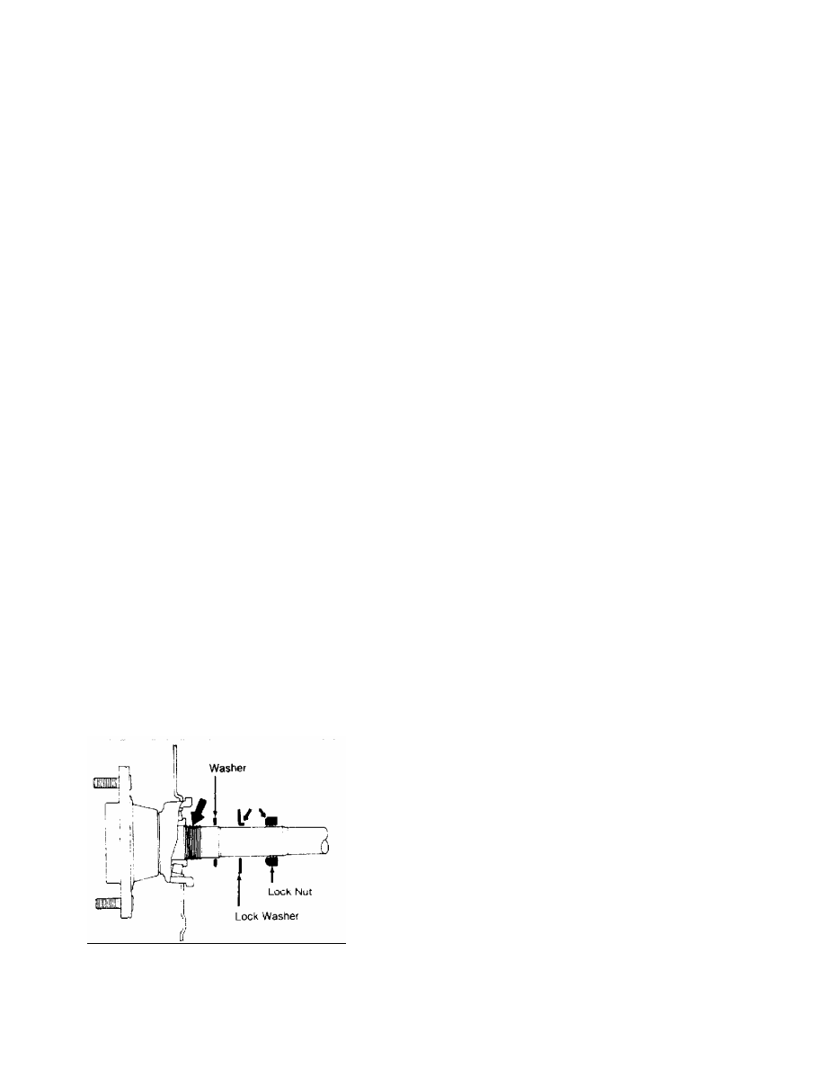
3) To remove wheel bearing, straighten lock washer tabs. See
Fig. 9. Remove lock nut using spanner wrench. Remove lock washer.
Install lock nut 3 turns on axle shaft. Install Puller (MB990787-01)
to remove axle shaft from bearing case. Rotate nuts with equal force
to remove axle shaft. Remove bearing outer race using a hammer and
drift.
Fig. 9: Removing Rear Axle Bearing (Montero)
Courtesy of Mitsubishi Motor Sales of America.
Installation
1) Apply Multipurpose Grease (SAE J310) to oil seal. Install
Нет комментариевНе стесняйтесь поделиться с нами вашим ценным мнением.
Текст