Mitsubishi Montero (1991+). Manual — part 57
CRUISE CONTROL SYSTEM
1991 Mitsubishi Montero
1991-92 SAFETY EQUIPMENT
Mitsubishi Cruise Control Systems
Montero
DESCRIPTION & OPERATION
The cruise control system is electronically and vacuum
controlled. System components include a control unit, actuator, vacuum
pump, cruise control switch, clutch pedal switch, cruise indicator
light, diode, inhibitor switch (A/T), stoplight switch, vehicle speed
sensor and A/T control unit.
The system has self-diagnostic capability. When
self-diagnostic mode is activated, each switch and sensor is checked
for defects. When cruise control system has been cancelled without
using a normal cancel method, a code will be set and stored in control
unit. Codes can be retrieved to help determine which circuit is
malfunctioning.
PRELIMINARY INSPECTION
Before performing TROUBLE SHOOTING steps, inspect linkage
assembly, actuator, cables and vacuum hoses. Ensure linkage and cables
move smoothly. Ensure cables do not have excessive slack or tension.
TROUBLE SHOOTING
NOTE: For further trouble shooting information, see CHECK RESULTS
& SYMPTOM CHARTS. See Figs. 11-16.
SYSTEM CANCELS OR WILL NOT RESET AFTER CANCELLATION
1) Check trouble codes, see SELF-DIAGNOSTICS under DIAGNOSIS
& TESTING. If no trouble codes are stored, ensure cruise control can
be set.
2) If cruise control can be set, system may have cancelled
because of driving on steep hills or loose wiring connection. If
cruise control still cannot be set, perform SYSTEM INPUT TESTS under
DIAGNOSIS & TESTING.
3) On 1991 models, if SYSTEM INPUT TESTS check okay, check
actuator circuit. See TEST NO. 5 under CIRCUIT TESTS (1991). On 1992
models, if SYSTEM INPUT TESTS check okay, check vacuum pump circuit.
See TEST NO. 6 under CIRCUIT TESTS (1992). On all models, if SYSTEM
INPUT TESTS do not check okay, see INPUT CODE CHART. See Fig. 9 or 10.
ADJUSTMENTS
CRUISE CONTROL CABLE
1991
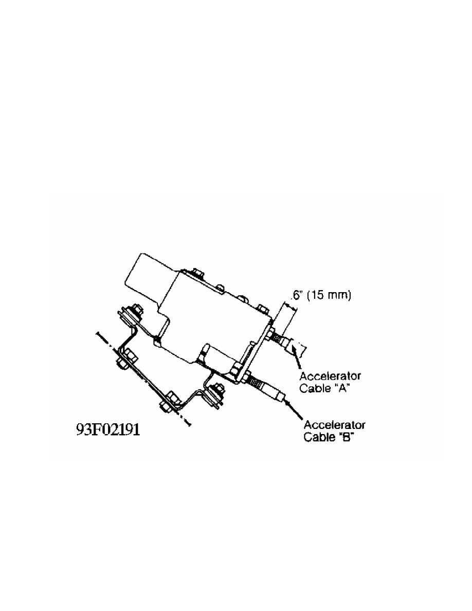
1) Ensure cruise control and accelerator cables are free of
bends and folds. Remove actuator cover. Loosen lock nuts and adjusting
nuts to free cables. Adjust accelerator cable "A" to correct
dimension. See Fig. 1 or 2.
2) Tighten lock nuts. Loosen adjustment bolts on intake air
plenum. Adjust plate so that inner cable free play is .04-.08" (1-2
mm). Tighten adjustment plate bolts.
3) Ensure throttle link is touching fixed Speed Adjusting
Screw (SAS). With intermediate link "A" in contact with stopper,
tighten adjusting nut "A" in direction that reduces inner cable free
play. See Fig. 3.
4) Stop turning adjusting nut "A" just before intermediate
link "A" begins to move. Back off adjusting nut "A" 1/2 turn. Inner
cable free play should be 0-.04" (0-1 mm). Tighten lock nut. Ensure
the distance intermediate link "B" begins to move when selector of
actuator turns is 04-.08" (1-2 mm). See Fig. 4.
5) Press accelerator pedal to ensure intermediate links "A"
and "B" operate smoothly. Install actuator cover.
Fig. 1: Adjusting Cruise Control & Accelerator Cables (1991 - 1 Of 4)
Courtesy of Mitsubishi Motor Co.
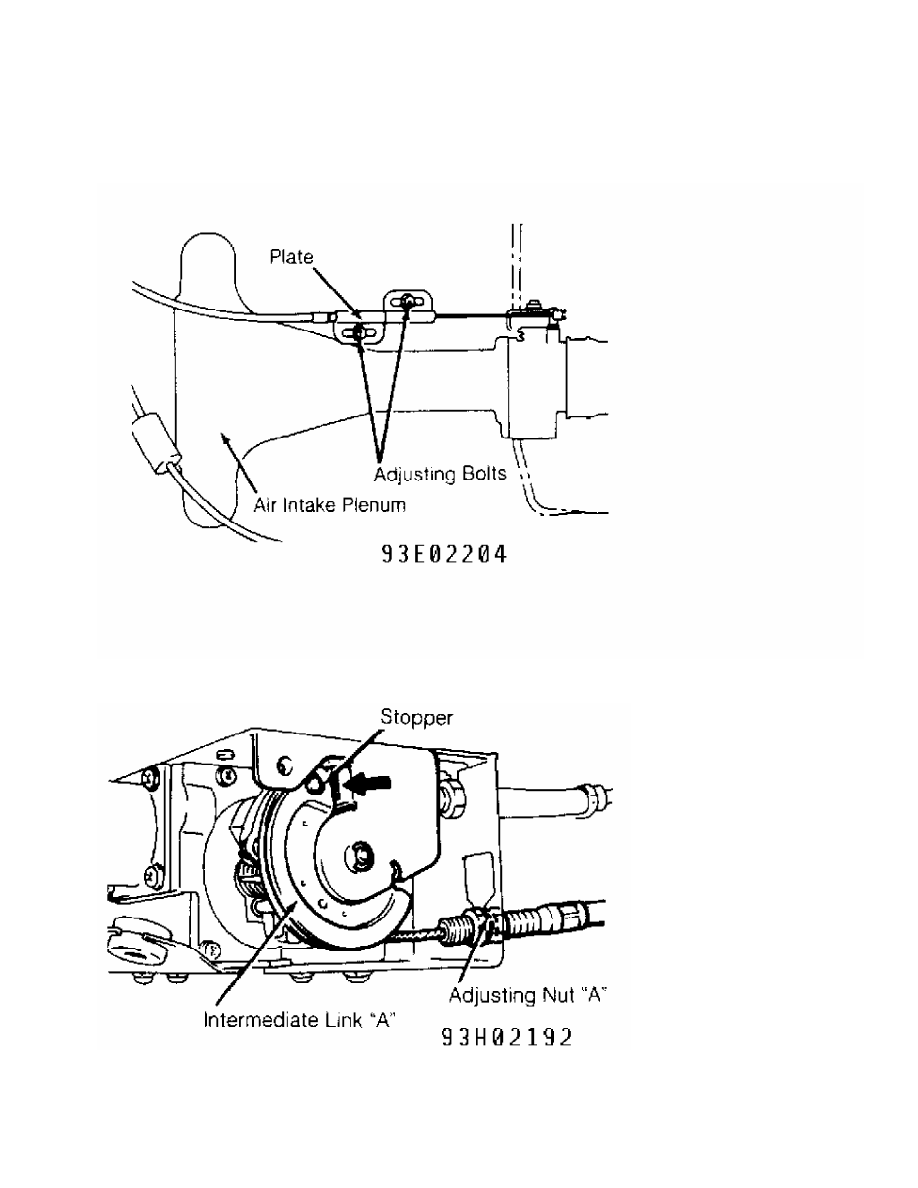
Fig. 2: Adjusting Cruise Control & Accelerator Cables (1991 - 2 Of 4)
Courtesy of Mitsubishi Motor Co.
Fig. 3: Adjusting Cruise Control & Accelerator Cables (1991 - 3 Of 4)
Courtesy of Mitsubishi Motor Co.
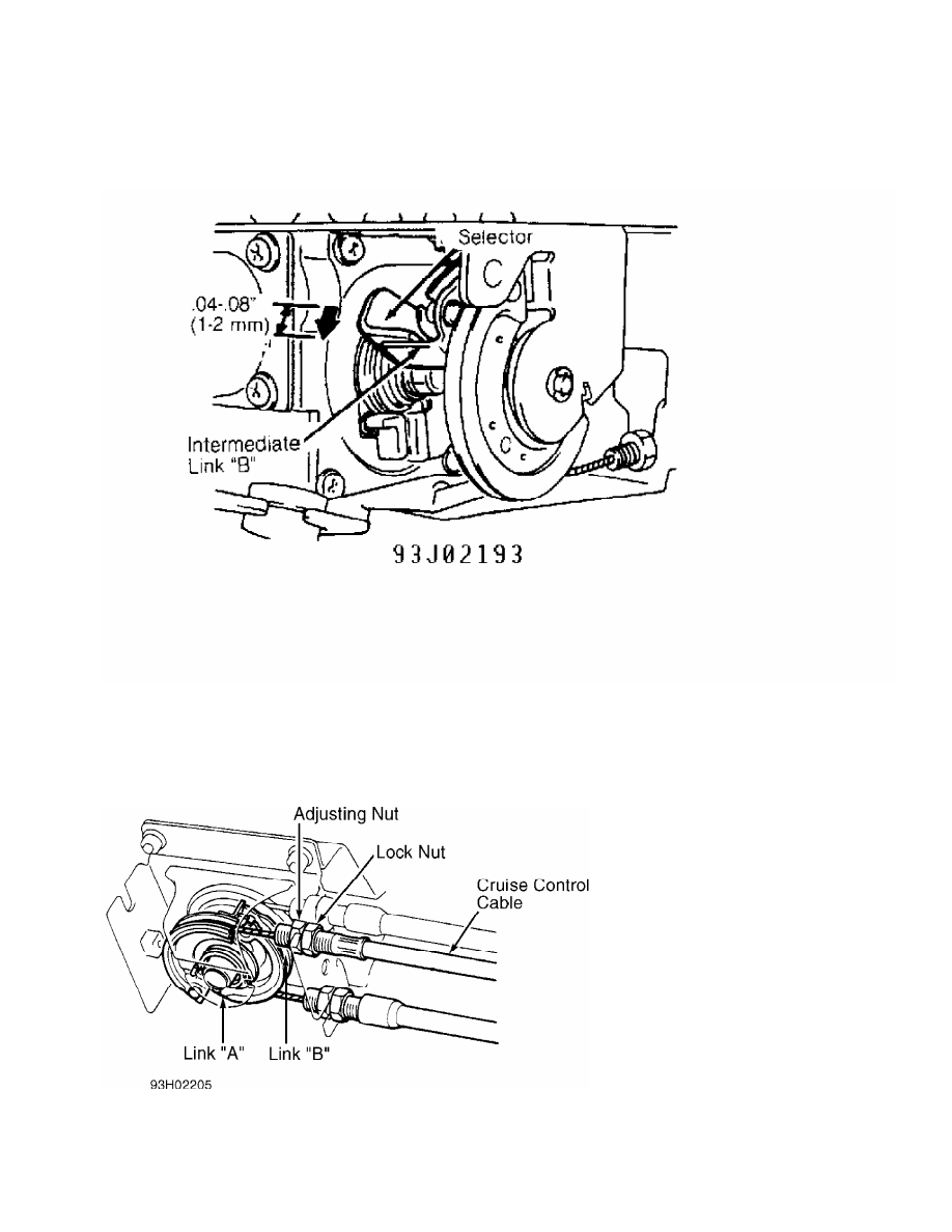
Fig. 4: Adjusting Cruise Control & Accelerator Cables (1991 - 4 Of 4)
Courtesy of Mitsubishi Motor Co.
1992
Remove link protector. Loosen lock nut. Hold link "A" so that
it touches link "B". Adjust free play by turning adjusting nut until
free play is .04-.08" (1-2 mm). Tighten lock nut. See Fig. 5.
Fig. 5: Adjusting Cruise Control Cable (1992)
Courtesy of Mitsubishi Motor Co.
DIAGNOSIS & TESTING
Нет комментариевНе стесняйтесь поделиться с нами вашим ценным мнением.
Текст