Mitsubishi Montero (1991+). Manual — part 114

PISTON & CONNECTING ROD INSTALLATION
Cylinders must be honed prior to piston installation. See
CYLINDER HONING under CYLINDER BLOCK in this article.
Install upper connecting rod bearings. Lubricate upper
bearings with engine oil. Install lower bearings in rod caps. Ensure
bearing tabs are properly seated. Position piston ring gaps according
to manufacturers recommendations. See Fig. 16. Lubricate pistons,
rings and cylinder walls.
Fig. 16: Typical Piston Ring End Gap Positioning - Typical
This Graphic For General Information Only
Install ring compressor. Use care not to rotate piston rings.
Compress rings with ring compressor. Install plastic tubing protectors

over connecting rod bolts. Install piston and connecting rod assembly.
Ensure piston notch, arrow or "FRONT" mark is toward front of engine.
See Fig. 17.
Fig. 17: Installing Piston & Connecting Rod Assembly - Typical
This Graphic For General Information Only
Carefully tap piston into cylinder until rod bearing is
seated on crankshaft journal. Remove protectors. Install rod cap and
bearing. Lightly tighten connecting rod bolts. Repeat procedure for
remaining cylinders. Check bearing clearance. See
MAIN & CONNECTING ROD BEARING CLEARANCE in this article.
Once clearance is checked, lubricate journals and bearings.
Install bearing caps. Ensure marks are aligned on connecting rod and
cap. Tighten rod nuts or bolts to specification. Ensure rod moves
freely on crankshaft. Check connecting rod side clearance. See
CONNECTING ROD SIDE CLEARANCE in this article.
CONNECTING ROD SIDE CLEARANCE
Position connecting rod toward one side of crankshaft as far
as possible. Using feeler gauge, measure clearance between side of
connecting rod and crankshaft. See Fig. 18. Clearance must be within
specifications.
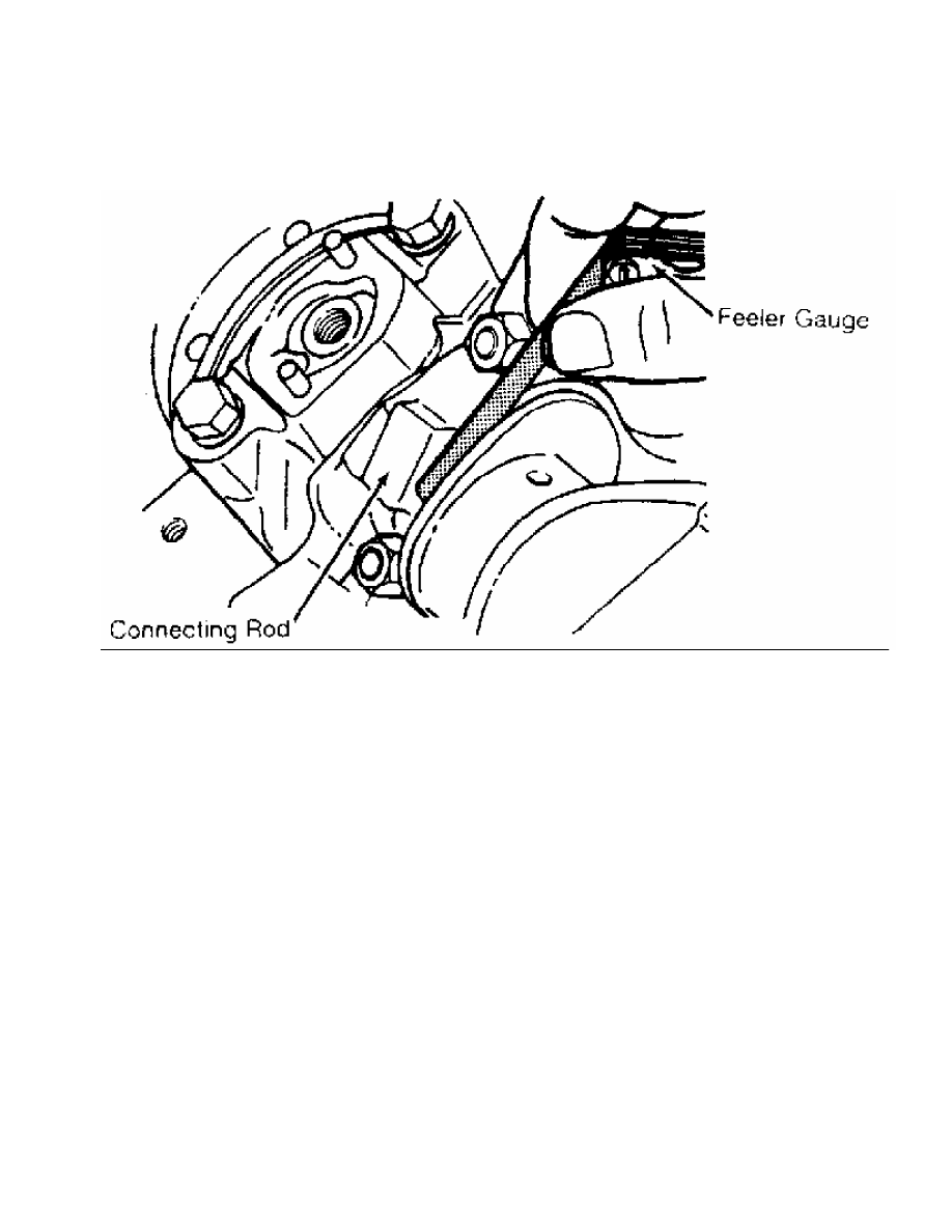
Fig. 18: Measuring Connecting Rod Side Clearance - Typical
This Graphic For General Information Only
Check for improper bearing installation, wrong bearing cap
or insufficient bearing clearance if side clearance is insufficient.
Connecting rod may require machining to obtain proper clearance.
Excessive clearance usually indicates excessive wear at crankshaft.
Crankshaft must be repaired or replaced.
MAIN & CONNECTING ROD BEARING CLEARANCE
Plastigage Method
Plastigage method may be used to determine bearing clearance.
Plastigage can be used with an engine in service or during reassembly.
Plastigage material is oil soluble.
Ensure journals and bearings are free of oil or solvent.
Oil or solvent will dissolve material and false reading will be
obtained. Install small piece of Plastigage along full length of
bearing journal. Install bearing cap in original location. Tighten
bolts to specification.
CAUTION: DO NOT rotate crankshaft while Plastigage is installed.
Bearing clearance will not be obtained if crankshaft is
rotated.
Remove bearing cap. Compare Plastigage width with scale on
Plastigage container to determine bearing clearance. See Fig. 19.
Rotate crankshaft 90 degrees. Repeat procedure. this is done to check
journal eccentricity. This procedure can be used to check oil
clearance on both connecting rod and main bearings.
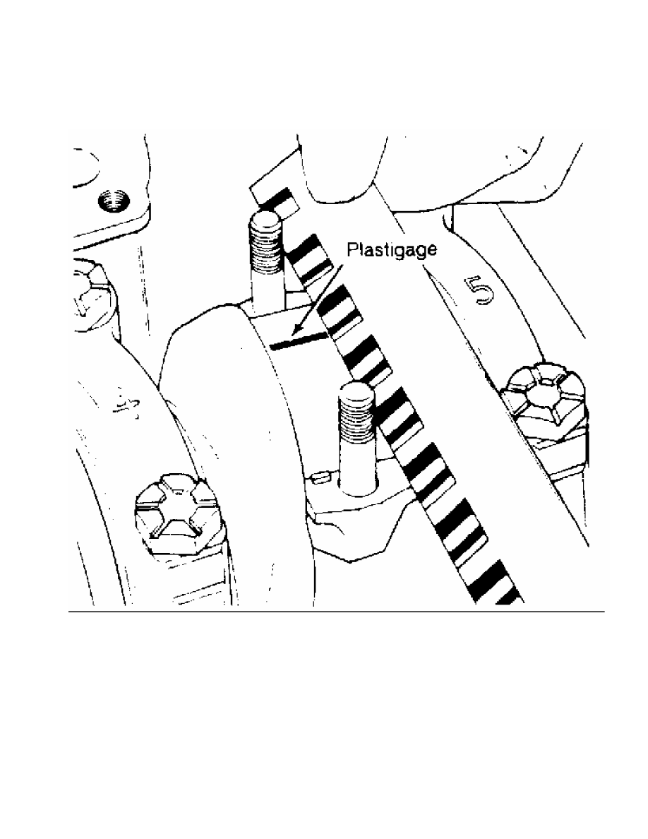
Fig. 19: Measuring Bearing Clearance - Typical
This Graphic For General Information Only
Micrometer & Telescopic Gauge Method
A micrometer is used to determine journal diameter, taper and
out-of-round dimensions of the crankshaft. See CLEANING & INSPECTION
under CRANKSHAFT & MAIN BEARINGS in this article.
With crankshaft removed, install bearings and caps in
original location on cylinder block. Tighten bolts to specification.
On connecting rods, install bearings and caps on connecting rods.
Install proper connecting rod cap on corresponding rod. Ensure bearing
cap is installed in original location. Tighten bolts to specification.
Using a telescopic gauge and micrometer or inside micrometer
measure inside diameter of connecting rod and main bearings bores.
Subtract each crankshaft journal diameter from the corresponding
inside bore diameter. This is the bearing clearance.
Нет комментариевНе стесняйтесь поделиться с нами вашим ценным мнением.
Текст