Mitsubishi Montero (1991+). Manual — part 113
interchangeable. Inspect all components for wear. Note amount of wear
in lifter body-to-camshaft contact area. Surface must have smooth and
convex contact face. If wear is apparent, carefully inspect cam lobe.
Inspect push rod contact area and lifter body for scoring
or signs of wear. If body is scored, inspect lifter bore for damage
and lack of lubrication. On roller type lifters, inspect roller for
flaking, pitting, loss of needle bearings and roughness during
rotation.
Measure lifter body O.D. in several areas. Measure lifter
bore I.D. of cylinder block. Some models offer oversized lifters.
Replace lifter if damaged.
If lifter check valve is not operating, obstructions may be
preventing it from closing or valve spring may be broken. Clean or
replace components as necessary.
Check plunger operation. Plunger should drop to bottom of the
body by its own weight when assembled dry. If plunger is not free,
soak lifter in solvent to dissolve deposits.
Lifter leak-down test can be performed on lifter. Lifter
must be filled with special test oil. New lifters contain special test
oil. Using lifter leak-down tester, perform leak-down test following
manufacturer’s instructions. If leak-down time is not within
specifications, replace lifter assembly.
Lifters should be soaked in clean engine oil several hours
prior to installation. Coat lifter base, roller (if equipped) and
lifter body with ample amount of Molykote or camshaft lubricant. See
Fig. 13. Install lifter in original location. Install remaining
components. Valve lash adjustment is not required on most hydraulic
lifters. Preload of hydraulic lifter is automatic. Some models may
require adjustment.
Mechanical Lifters
Lifter assemblies must be installed in original locations.
Remove rocker arm assembly and push rod. Mark components for location.
Some applications require intake manifold or lifter cover removal.
Remove lifter retainer plate (if used). To remove lifters, use lifter
remover or magnet.
Inspect push rod contact area and lifter body for scoring or
signs of wear. If body is scored, inspect lifter bore for damage and
lack of lubrication. Note amount of wear in lifter body-to-camshaft
contact area. Surface must have smooth and convex contact face. If
wear is apparent, carefully inspect cam lobe.
Coat lifter base, roller (if equipped) and lifter body with
ample amount of Molykote or camshaft lubricant. Install lifter in
original location. Install remaining components. Tighten bolts to
specification. Adjust valves. See VALVE ADJUSTMENT in this article.
PISTONS, CONNECTING RODS & BEARINGS
* PLEASE READ THIS FIRST *
NOTE: Always refer to appropriate engine overhaul article in the
ENGINES section for complete overhaul procedures and
specifications for the vehicle being repaired.
RIDGE REMOVAL
Ridge in cylinder wall must be removed prior to piston
removal. Failure to remove ridge prior to removing pistons will cause
piston damage in piston ring locations.
With the piston at bottom dead center, place a rag in the
bore to trap metal chips. Install ridge reamer in cylinder bore.
Adjust ridge reamer using manufacturer’s instructions. Remove ridge
using ridge reamer. DO NOT remove an excessive amount of material.
Ensure ridge is completely removed.
PISTON & CONNECTING ROD REMOVAL
Note top of piston. Some pistons may contain a notch, arrow
or be marked "FRONT". Piston must be installed in proper direction to
prevent damage with valve operation.
Check that connecting rod and cap are numbered for cylinder
location and which side of cylinder block the number faces. Proper cap
and connecting rod must be installed together. Connecting rod cap must
be installed on connecting rod in proper direction to ensure bearing
lock procedure. Mark connecting rod and cap if necessary. Pistons must
be installed in original location.
Remove cap retaining nuts or bolts. Remove bearing cap.
Install stud protectors on connecting rod bolts. This protects
cylinder walls from scoring during removal. Ensure proper removal of
ridge. Push piston and connecting rod from cylinder. Connecting rod
boss can be tapped with a wooden dowel or hammer handle to aid in
removal.
PISTON & CONNECTING ROD
Disassembly
Using ring expander, remove piston rings. Remove piston pin
retaining rings (if equipped). On pressed type piston pins, special
fixtures and procedures according to manufacturer must be used to
remove piston pins. Follow manufacturer’s recommendations to avoid
piston distortion or breakage.
Cleaning
Remove all carbon and varnish from piston. Pistons and
connecting rods may be cleaned in cold type chemical tank. Using ring
groove cleaner, clean all deposits from ring grooves. Ensure all
deposits are cleaned from ring grooves to prevent ring breakage or
sticking. DO NOT attempt to clean pistons using wire brush.
Inspection
Inspect pistons for nicks, scoring, cracks or damage in ring
areas. Connecting rod should be checked for cracks using Magnaflux
procedure. Piston diameter must be measured in manufacturers specified
area.
Using telescopic gauge and micrometer, measure piston pin
bore of piston in 2 areas, 90 degrees apart. This is done to check
diameter and out-of-round.
Install proper bearing cap on connecting rod. Ensure bearing
cap is installed in proper location. Tighten bolts or nuts to
specification. Using inside micrometer, measure inside diameter in 2
areas, 90 degrees apart.
Connecting rod I.D. and out-of-round must be within
specification. Measure piston pin bore I.D. and piston pin O.D. All
components must be within specification. Subtract piston pin diameter
from piston pin bore in piston and connecting rod to determine proper
fit.
Connecting rod length must be measured from center of
crankshaft journal inside diameter to center of piston pin bushing
using proper caliper. Connecting rods must be the same length.
Connecting rods should be checked on an alignment fixture for bent or
twisted condition. Replace all components which are damaged or not
within specification.
PISTON & CYLINDER BORE FIT

Ensure cylinder is checked for taper, out-of-round and
properly honed prior to checking piston and cylinder bore fit. See
CYLINDER BLOCK in this article. Using dial bore gauge, measure
cylinder bore. Measure piston at right angle to piston pin in center
of piston skirt area. Subtract piston diameter from cylinder bore
diameter. The difference is piston-to-cylinder clearance. Clearance
must be within specification. Mark piston for proper cylinder
location.
ASSEMBLING PISTON & CONNECTING ROD
Install proper fitted piston on connecting rod for proper
cylinder. Ensure piston marking on top of piston marked is in
correspondence with connecting rod and cap number. See Fig. 14.
Fig. 14: Piston Pin Installation - Typical
This Graphic For General Information Only
Lubricate piston pin and install in connecting rod. Ensure
piston pin retainers are fully seated (if equipped). On pressed type
piston pins, follow manufacturer’s recommended procedure to avoid
distortion or breakage.
CHECKING PISTON RING CLEARANCES
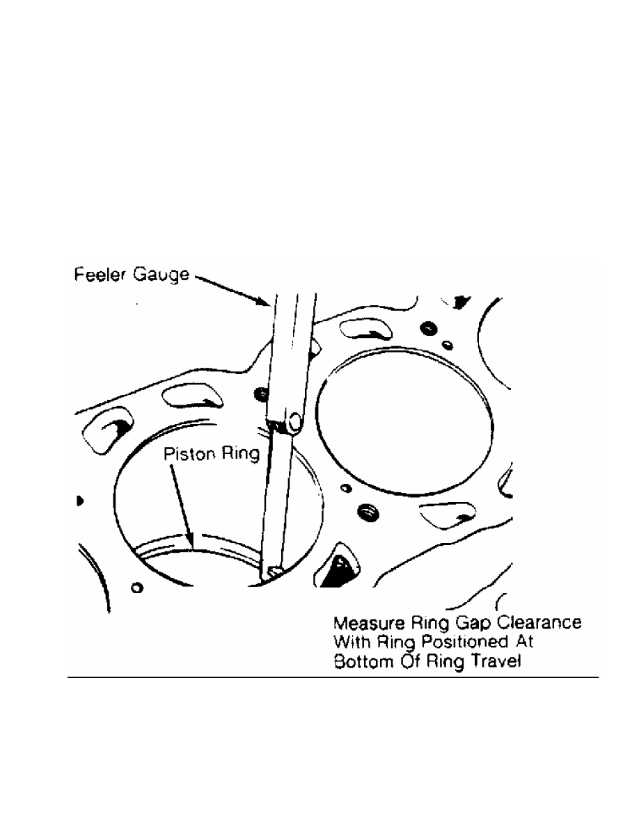
Piston rings must be checked for side clearance and end gap.
To check end gap, install piston ring in cylinder which it is to be
installed. Using an inverted piston, push ring to bottom of cylinder
in smallest cylinder diameter.
Using feeler gauge, check ring end gap. See Fig. 15. Piston
ring end gap must be within specification. Ring breakage will occur
with insufficient ring end gap.
On some manufacturers, insufficient ring end gap may be
corrected by using a fine file while other manufacturers recommend
using another ring set. Mark rings for proper cylinder installation
after checking end gap.
Fig. 15: Checking Piston Ring End Gap - Typical
This Graphic For General Information Only
For checking side clearance, install rings on piston. Using
feeler gauge, measure clearance between piston ring and piston ring
land. Check side clearance in several areas around piston. Side
clearance must be within specification.
If side clearance is excessive, piston ring grooves can be
machined to accept oversized piston rings (if available). Normal
practice is to replace piston.
Нет комментариевНе стесняйтесь поделиться с нами вашим ценным мнением.
Текст