Mitsubishi Montero (1991+). Manual — part 115
CRANKSHAFT & MAIN BEARINGS
* PLEASE READ THIS FIRST *
NOTE: Always refer to appropriate engine overhaul article in the
ENGINES section for complete overhaul procedures and
specifications for the vehicle being repaired.
REMOVAL
Ensure all main bearing caps are marked for location on
cylinder block. Some main bearing caps have an arrow stamped on it
which must face front of engine. Remove main bearing cap bolts. Remove
main bearing caps. Carefully remove crankshaft. Use care not to bind
crankshaft in cylinder block during removal.
CLEANING & INSPECTION
Thoroughly clean crankshaft using solvent. Dry with
compressed air. Ensure all oil passages are clear and free of sludge,
rust, dirt, and metal chips.
Inspect crankshaft for scoring and nicks. Inspect crankshaft
for cracks using Magnaflux procedure. Inspect rear seal area for
grooving or damage. Inspect bolt hole threads for damage. If pilot
bearing or bushing is used, check pilot bearing or bushing fit in
crankshaft. Inspect crankshaft gear for damaged or cracked teeth.
Replace gear if damaged. Check that oil passage plugs are tight (if
equipped).
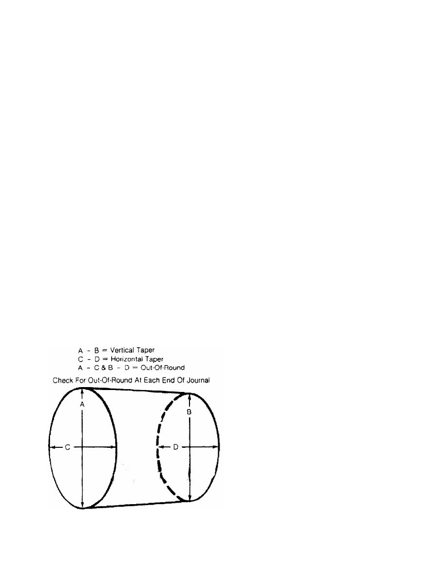
Using micrometer, measure all journals in 4 areas to
determine journal taper, out-of-round and undersize. See Fig. 20.
Some crankshafts can be reground to the next largest undersize,
depending on the amount of wear or damage. Crankshafts with rolled
fillet cannot be reground and must be replaced.
Fig. 20: Measuring Crankshaft Journal - Typical
This Graphic For General Information Only
Crankshaft journal runout should be checked. Install
crankshaft in "V" blocks or bench center. Position dial indicator
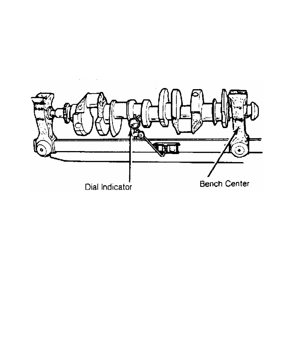
with tip resting on the main bearing journal area. See Fig. 21.
Rotate crankshaft and note reading. Journal runout must not exceed
specification. Repeat procedure on all main bearing journals.
Crankshaft must be replaced if runout exceeds specification.
Fig. 21: Measuring Crankshaft Main Bearing Journal Runout - Typical
This Graphic For General Information Only
INSTALLATION
Install upper main bearing in cylinder block. Ensure lock
tab is properly located in cylinder block. Install bearings in main
bearing caps. Ensure all oil passages are aligned. Install rear seal
(if removed).
Ensure crankshaft journals are clean. Lubricate upper main
bearings with clean engine oil. Carefully install crankshaft. Check
each main bearing clearance using Plastigage method. See
MAIN & CONNECTING ROD BEARING CLEARANCE in this article.
Once clearance is checked, lubricate lower main bearing and
journals. Install main bearing caps in original location. Install rear
seal in rear main bearing cap (if removed). Some rear main bearing
caps require sealant to be applied in corners to prevent oil leakage.
Install and tighten all bolts except thrust bearing cap to
specification. Tighten thrust bearing cap bolts finger tight only.
Thrust bearing must be aligned. On most applications, crankshaft
must be moved rearward then forward. Procedure may vary with
manufacturer. Thrust bearing cap is then tighten to specification.
Ensure crankshaft rotates freely. Crankshaft end play should be
checked. See CRANKSHAFT END PLAY in this article.
CRANKSHAFT END PLAY
Dial Indicator Method
Crankshaft end play can be checked using dial indicator.
Mount dial indicator on rear of cylinder block. Position dial
indicator tip against rear of crankshaft. Ensure tip is resting
against flat surface.
Pry crankshaft rearward. Adjust dial indicator to zero.
Pry crankshaft forward and note reading. Crankshaft end play must be
within specification. If end play is not within specification, check
for faulty thrust bearing installation or worn crankshaft. Some
applications offer oversized thrust bearings.
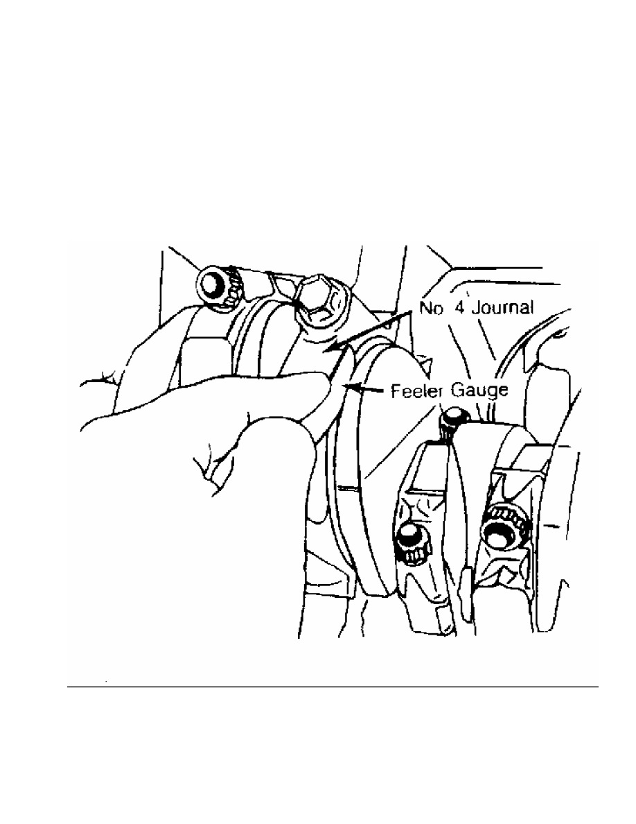
Feeler Gauge Method
Crankshaft end play can be checked using feeler gauge. Pry
crankshaft rearward. Pry crankshaft forward. Using feeler gauge,
measure clearance between crankshaft and thrust bearing surface. See
Fig. 22.
Fig. 22: Checking Crankshaft End Play - Typical
This Graphic For General Information Only
Crankshaft end play must be within specification. If end
play is not within specification, check for faulty thrust bearing
installation or worn crankshaft. Some applications offer oversized
thrust bearings.
CYLINDER BLOCK
* PLEASE READ THIS FIRST *
NOTE: Always refer to appropriate engine overhaul article in the
ENGINES section for complete overhaul procedures and
specifications for the vehicle being repaired.
BLOCK CLEANING
Only cast cylinder blocks should be hot tank cleaned.
Aluminum cylinder blocks should be cleaned using cold tank method.
Cylinder block is cleaned in order to remove carbon deposits, gasket
residue and water jacket scale. Remove oil galley plugs, freeze plugs
and cam bearings prior to block cleaning.
BLOCK INSPECTION
Visually inspect the block. Check suspected areas for cracks
using the Dye Penetrant inspection method. Block may be checked for
cracks using the Magnaflux method.
Cracks are most commonly found at the bottom of the
cylinders, the main bearing saddles, near expansion plugs and between
the cylinders and water jackets. Inspect lifter bores for damage.
Inspect all head bolt holes for damaged threads. Threads should be
cleaned using tap to ensure proper head bolt torque. Consult machine
shop concerning possible welding and machining (if required).
CYLINDER BORE INSPECTION
Inspect the bore for scuffing or roughness. Cylinder bore
is dimensionally checked for out-of-round and taper using dial bore
gauge. For determining out-of-round, measure cylinder parallel and
perpendicular to the block centerline. Difference in the 2 readings
is the bore out-of-round. Cylinder bore must be checked at top, middle
and bottom of piston travel area.
Bore taper is obtained by measuring bore at the top and
bottom. If wear has exceeded allowable limits, block must be honed
or bored to next available oversize piston dimension.
CYLINDER HONING
Cylinder must be properly honed to allow new piston rings to
properly seat. Cross-hatching at correct angle and depth is critical
to lubrication of cylinder walls and pistons.
A flexible drive hone and power drill are commonly used.
Drive hone must be lubricated during operation. Mix equal parts of
kerosene and SAE 20w engine oil for lubrication.
Apply lubrication to cylinder wall. Operate cylinder hone
from top to bottom of cylinder using even strokes to produce 45 degree
cross-hatch pattern on the cylinder wall. DO NOT allow cylinder hone
to extend below cylinder during operation.
Recheck bore dimension after final honing. Wash cylinder
wall with hot soapy water to remove abrasive particles. Blow dry with
compressed air. Coat cleaned cylinder walls with lubricating oil.
DECK WARPAGE
Check deck for damage or warped head sealing surface. Place
a straightedge across gasket surface of the deck. Using feeler gauge,
measure clearance at center of straightedge. Measure across width and
Нет комментариевНе стесняйтесь поделиться с нами вашим ценным мнением.
Текст