Mitsubishi Montero (1991+). Manual — part 157
FUEL GAUGE
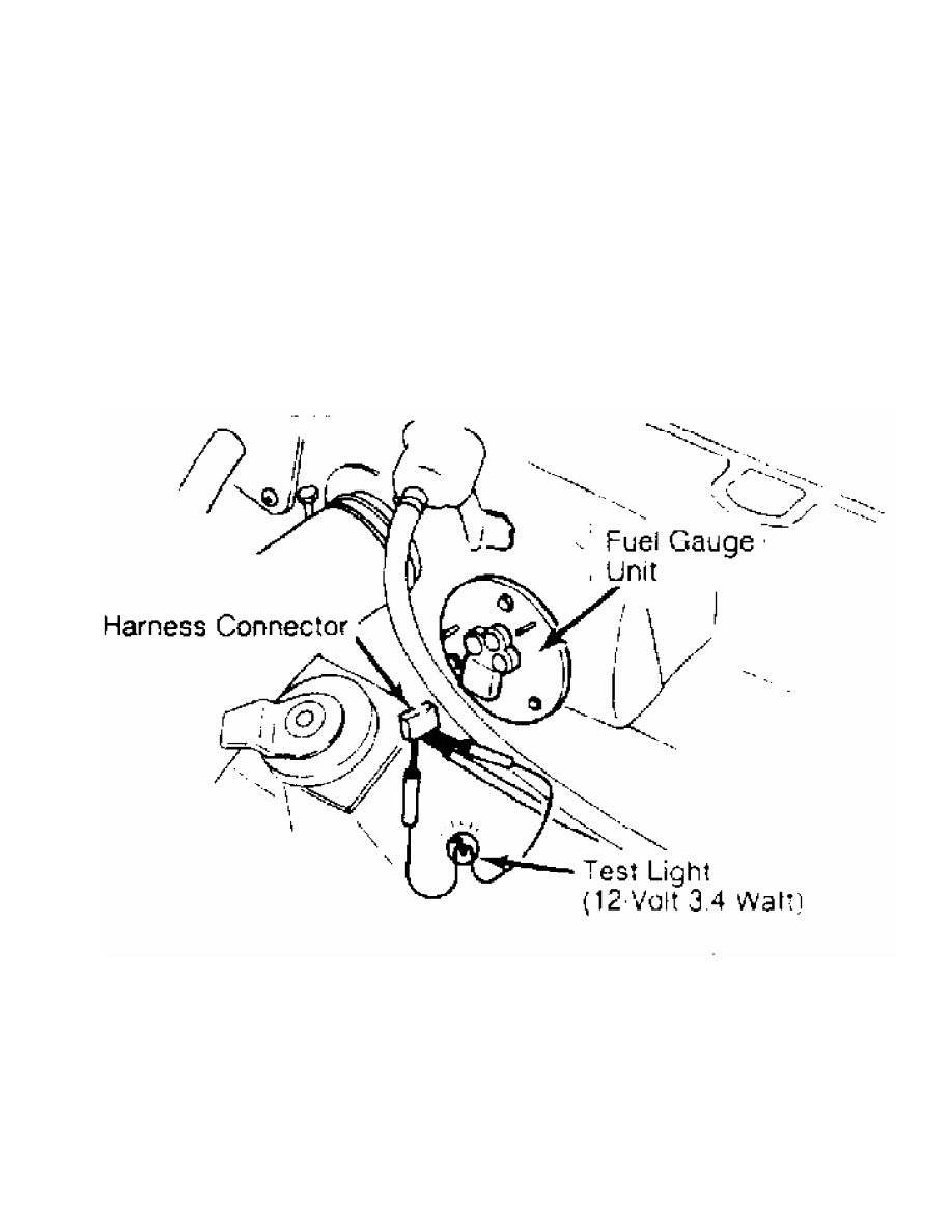
Simple Test
Disconnect fuel sending unit connector wire in luggage
compartment, cargo space, or at tank unit. Connect a 12-volt, 3.4-watt
bulb to harness side of connector, between power terminal and ground
(Yellow and Black wires on Montero). On Pickup and Ram-50 see Fig. 1.
Turn ignition switch to ON position. Ensure test bulb flashes, or
stays on, and fuel gauge needle moves. If bulb or gauge needle does
not function as described, check and repair fuel gauge circuit.
CAUTION: Gauge coils can be damaged if wire is grounded too long.
Perform test as quickly as possible.
Fig. 1: Identifying Fuel Gauge Test Connection (Pickup & Ram-50)
Courtesy of Chrysler Motors.
NOTE: The following test must be completed with instrument panel
cluster removed. Use ohmmeter for all measurements. If
resistance is extremely low, there may be a short in the
coil. If resistance is extremely high, there may be a broken
wire or similar problem in the gauge.
Resistance Test
Remove instrument cluster. See INSTRUMENT CLUSTER under
REMOVAL & INSTALLATION. Measure resistance between appropriate
terminals of instrument cluster or combination gauges. See Fig. 2 or

Fig. 3. See FUEL GAUGE RESISTANCE SPECIFICATIONS table. If resistance
readings are not to specifications, replace fuel gauge.
FUEL GAUGE RESISTANCE SPECIFICATIONS TABLE
Application Terminals Ohms
Montero . . . . . No. 1 & 2 . . . . . . 55
" . . . . . . .. No. 2 & 3 . . . . . ... 165
" . . . . . . .. No. 1 & 3 . . . . . ... 110
Pickup & Ram-50 . . .. IGN & ground. . . . . ... 62-78
" . . . . . . ... 7V & FU . . . . . .. 49-61
Fig. 2: Fuel Gauge Resistance Check Terminal ID (Montero)
Courtesy of Mitsubishi Motor Sales of America.
Fig. 3: Fuel Gauge Resistance Check Terminal ID (Pickup & Ram-50)
Courtesy of Mitsubishi Motor Sales of America.
OIL PRESSURE GAUGE
Circuit Test
Disconnect oil pressure gauge wiring connector from sending
unit inside the engine compartment. Connect a 12-volt test light
between harness connector terminal and ground. Turn ignition on, but
DO NOT start engine. If test light comes on and gauge needle moves, go
to GAUGE RESISTANCE TEST. If test light does not come on and gauge
needle does not move, repair wiring to sending unit.
Gauge Resistance Test
Remove instrument cluster from instrument panel. See
INSTRUMENT CLUSTER under REMOVAL & INSTALLATION. Check continuity
between oil pressure gauge terminals. See Fig. 4 or Fig. 5. See
OIL PRESSURE GAUGE RESISTANCE SPECIFICATIONS table. If resistance is
not within specification, replace oil pressure gauge.
OIL PRESSURE GAUGE RESISTANCE SPECIFICATIONS TABLE
Application Ohms
Montero . . . . . . . . . .. 50
Pickup & Ram-50 . . . . . . ... 37-47
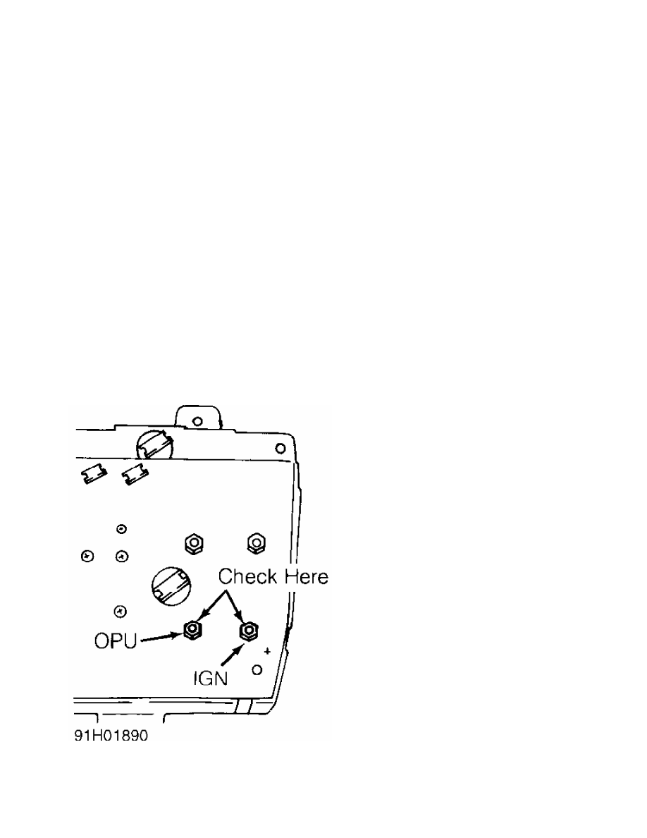
Fig. 4: Oil Pressure Gauge Test Terminal ID (Pickup & Ram-50)
Courtesy of Chrysler Motors
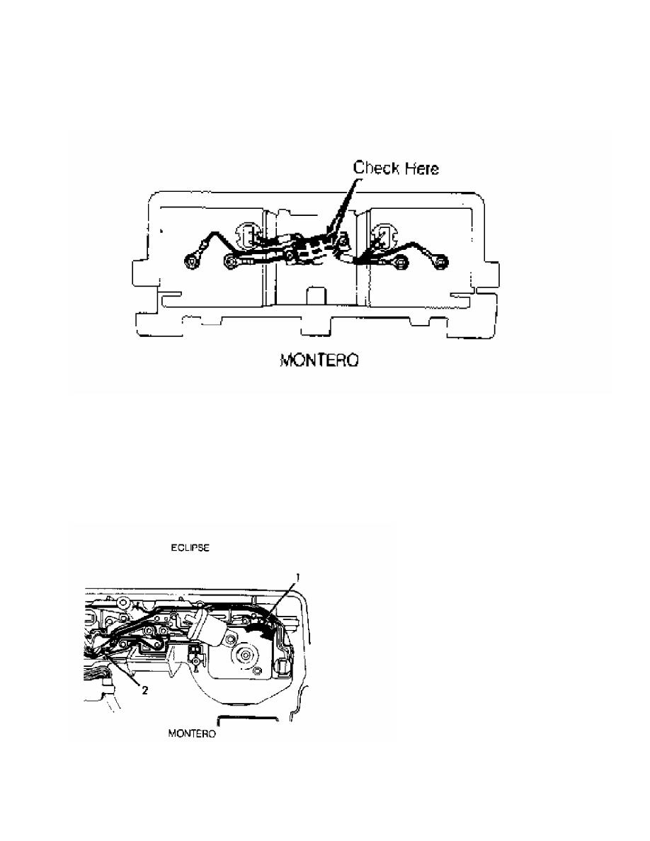
Fig. 5: Oil Pressure Gauge Test Terminal ID (Montero)
Courtesy of Chrysler Motors
REED SWITCH
Continuity Check (Except Pickup & Ram-50)
Remove instrument cluster. See INSTRUMENT CLUSTER under
REMOVAL & INSTALLATION. Check continuity between reed switch terminals
No. 1 and 2. See Fig. 6. Ensure continuity pulses on and off 4 times
per revolution of speedometer shaft connection. If continuity is not
as specified, replace reed switch.
Fig. 6: Identifying Reed Switch Test Terminals (Montero)
Courtesy of Mitsubishi Motor Sales of America.
SPEEDOMETER
Нет комментариевНе стесняйтесь поделиться с нами вашим ценным мнением.
Текст