Mitsubishi Montero (1991+). Manual — part 158
Calibration Test
Adjust tire pressure to standard value. Using a calibrated,
reliable speedometer tester, compare reading of vehicle speedometer to
speedometer tester. See SPEEDOMETER ALLOWABLE VARIATION table. Replace
speedometer if necessary.
SPEEDOMETER ALLOWABLE VARIATION TABLE
MPH (km/h) Allowable Variation MPH (km/h)
20 (32) . . . . . . .. 19-22 (31-35)
40 (64) . . . . . . .. 38-44 (61-71)
60 (97) . . . . . . . 57-66 (92-106)
80 (129) . . . . . ... 76-88 (122-142)
100 (161) . . . . . . 94-110 (151-177)
TACHOMETER
NOTE: DO NOT reverse polarity when installing tachometer, as diode
and transistor may be damaged.
Calibration Test
Connect a calibrated, reliable tach-dwell meter to vehicle
ignition system. Operate engine at various speeds (RPM). See
TACHOMETER ALLOWABLE VARIATION table. If comparison between tach-dwell
meter and vehicle tachometer readings do not fall in the standard
range of permissible variation, replace vehicle tachometer.
TACHOMETER ALLOWABLE VARIATION TABLE
Engine Speed (RPM) Allowable Variation (RPM)
1000 . . . . . . . . .. 900-1100
3000 . . . . . . . . . 2850-3150
5000 . . . . . . . . . 4750-5250
6000 . . . . . . . . . 5700-6300
TEMPERATURE GAUGE
CAUTION: DO NOT connect sender wire directly to ground during test.
Circuit Test
Disconnect temperature sender wire from sending unit. Connect
a 12-volt, 3.4-watt test bulb between connector terminal and ground.
Turn ignition switch to ON position. If test bulb flashes and
temperature gauge needle moves, go to SENSOR RESISTANCE TEST. If test
light does not flash and gauge needle does not move, repair wiring to
sending unit.
Sensor Resistance Test
Remove thermosensor (sending unit) from engine block. Place
sending unit in hot water of 158
F (70
C) temperature. Check sensor
resistance with an ohmmeter. Thermosensor resistance should be 90-117
ohms at 158
F (70
C). If thermosensor resistance in okay, go to GAUGE
RESISTANCE TEST. Replace thermosensor if resistance is not as
specified.
Gauge Resistance Test
Remove instrument cluster from instrument panel. See
INSTRUMENT CLUSTER under REMOVAL & INSTALLATION. Measure resistance
between temperature gauge terminals at rear of cluster or combination
gauges. See TEMPERATURE GAUGE RESISTANCE SPECIFICATIONS table. See
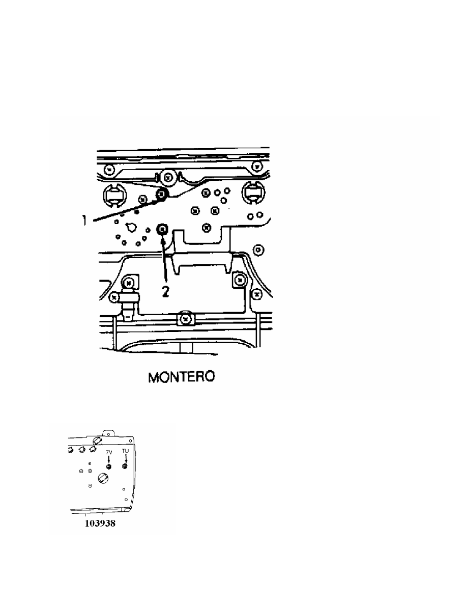
Fig. 7 or Fig. 8.
Fig. 7: Temperature Gauge Test Terminals (Montero)
Courtesy of Mitsubishi Motor Sales of America.
Fig. 8: Temperature Gauge Test Terminal ID (Pickup & Ram-50)
Courtesy of Mitsubishi Motor Sales of America.
TEMPERATURE GAUGE RESISTANCE SPECIFICATIONS TABLE

Application Terminals Ohms
Montero . . . ... No. 1 & 2 . . . 55
Pickup & Ram-50 . . 7V & TU . ... 49-61
VOLTMETER
Resistance Test (Montero)
Using an ohmmeter, measure resistance between voltmeter
terminals. See Fig. 9. Resistance should be 380-460 ohms.
Fig. 9: Identifying Voltmeter Resistance Test Terminals (Montero)
Courtesy of Mitsubishi Motor Sales of America.
Voltage Test (Pickup & Ram-50)
Using a voltmeter, connect positive lead to terminal No. 7 of
fuse box, and ground negative terminal. Crank engine and compare
readings of vehicle voltmeter to testing voltmeter. Voltage variation
should not exceed 0.5 volt (plus or minus). Replace voltmeter if
voltage reading is not as specified.
REMOVAL & INSTALLATION
INSTRUMENT CLUSTER
Removal & Installation (Montero)
1) Remove instrument cluster cover. Remove screws from bottom
of instrument cluster. Remove bolt from upper part of cluster.
2) Disconnect speedometer cable from back of instrument
cluster by pushing stopper of plug on speedometer cable side of
connection. Pull cluster out part way. Disconnect all connectors
attaching cluster. Remove cluster. See Fig. 10. To install, reverse
removal procedure.
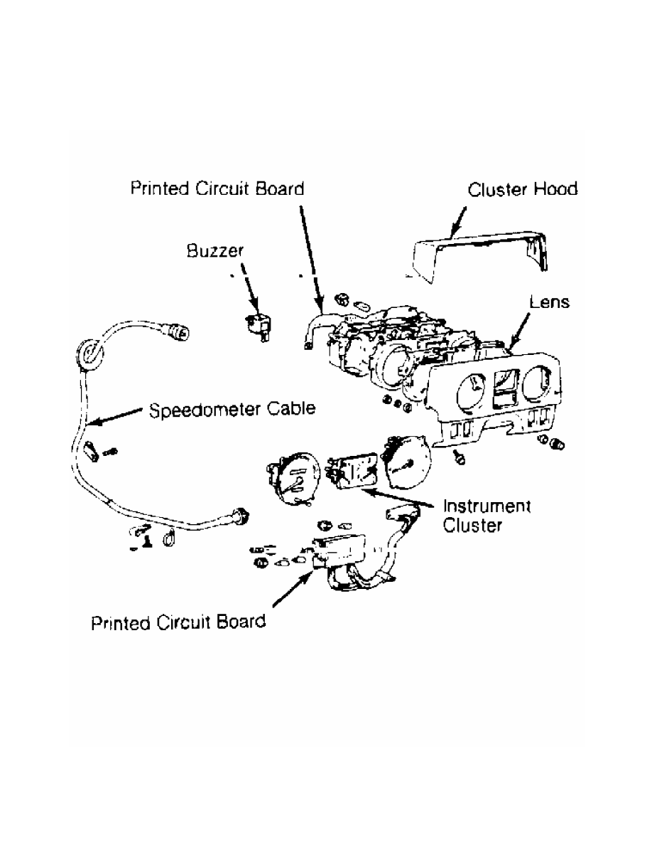
Fig. 10: Identifying Instrument Cluster Components (Montero)
Courtesy of Mitsubishi Motor Sales of America.
Removal & Installation (Pickup & Ram-50)
1) Disconnect negative battery cable. Remove heater fan
Нет комментариевНе стесняйтесь поделиться с нами вашим ценным мнением.
Текст