Mitsubishi Montero (1991+). Manual — part 155
HOW TO USE SYSTEM WIRING DIAGRAMS
1991 Mitsubishi Montero
GENERAL INFORMATION
Using Wiring Diagrams
All Models
INTRODUCTION
This CD obtains wiring diagrams and technical service
bulletins, containing wiring diagram changes from the domestic and
import manufacturers. These are checked for accuracy and are all
redrawn into a consistent format for easy use.
In the past, when cars were simpler, diagrams were simpler.
All components were connected by wires and diagrams seldom exceeded 4
pages in length. Today, some wiring diagrams require more than 16
pages. It would be impractical to expect a service technician to trace
a wire from page 1 across every page to page 16.
Removing some of the wiring maze reduces eyestrain and time
wasted searching across several pages. Today the majority of these
diagrams follow a much improved format, which permits space for
internal switch details.
Wiring diagrams are drawn in a "top-down" format. The
diagrams are drawn with the power source at the top of the diagram and
the ground point at the bottom of the diagram. Components locations
are identified on the wiring diagrams. Any wires that don’t connect
directly to a component are identified on the diagram to indicate
where they go.
COLOR ABBREVIATIONS
COLOR ABBREVIATIONS TABLE
Color Normal Optional
Black . . . . BLK . . . . . . .. BK
Blue . . . . . BLU . . . . . . .. BU
Brown . . . . BRN . . . . . . .. BN
Clear . . . . CLR . . . . . . .. CR
Dark Blue . . .. DK BLU . . . . . .. DK BU
Dark Green . . . DK GRN . . . . . .. DK GN
Green . . . . GRN . . . . . . .. GN
Gray . . . . . GRY . . . . . . .. GY
Light Blue . . . LT BLU . . . . . .. LT BU
Light Green . . LT GRN . . . . . .. LT GN
Orange . . . ... ORG . . . . . . .. OG
Pink . . . . . PNK . . . . . . .. PK
Purple . . . ... PPL . . . . . . .. PL
Red . . . . .. RED . . . . . . .. RD
Tan . . . . .. TAN . . . . . . .. TN
Violet . . . ... VIO . . . . . . .. VI
White . . . . WHT . . . . . . .. WT
Yellow . . . ... YEL . . . . . . .. YL
IDENTIFYING WIRING DIAGRAM ABBREVIATIONS
NOTE: Abbreviations used on these diagrams are normally
self-explanatory. If necessary see ABBREVIATIONS
article in GENERAL INFORMATION.
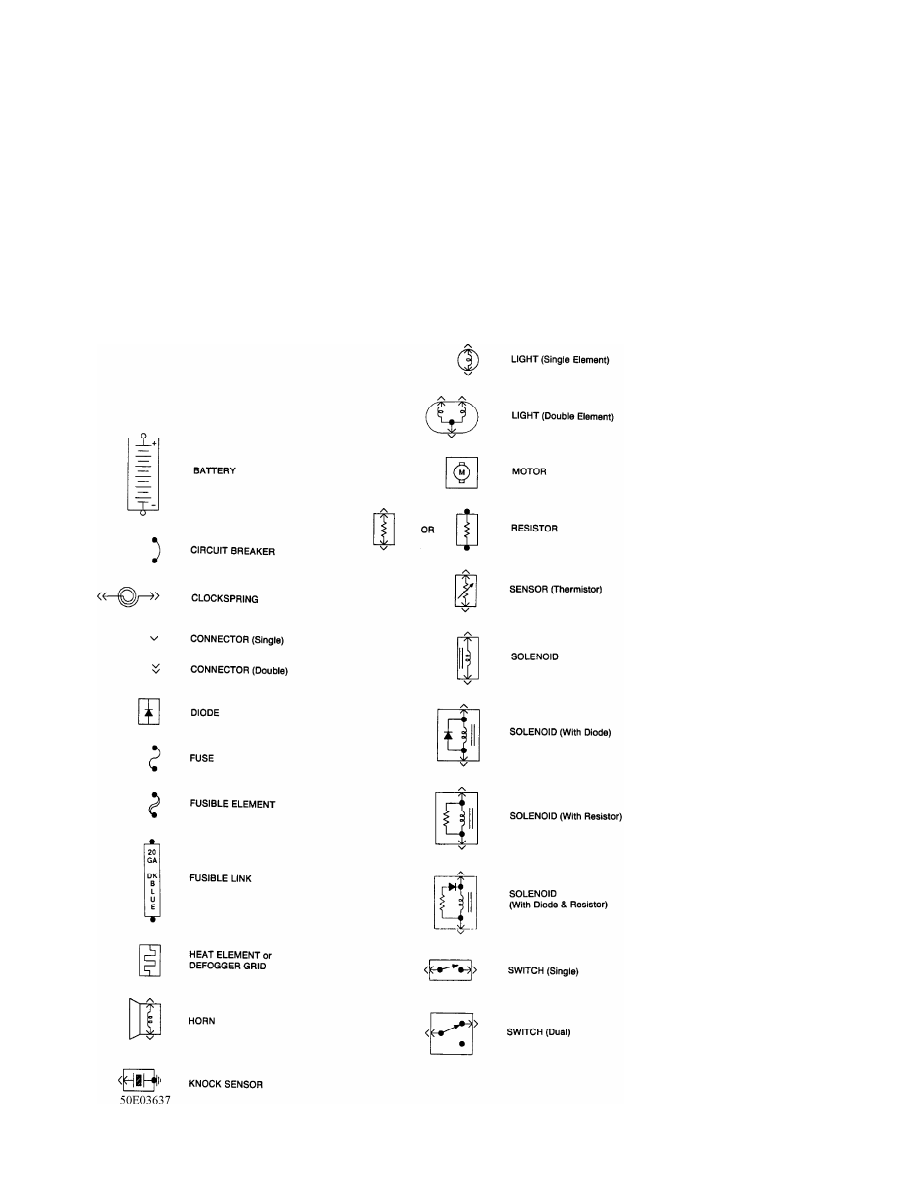
IDENTIFYING WIRING DIAGRAM SYMBOLS
NOTE: Standard wiring symbol are used in these diagrams. The
illustration below will help clarify any symbols that are
not easily understood at a glance. Most components are
labeled "Motor", "Switch" or "Relay" in addition to being
drawn with the standard symbol.
Fig. 1: Identifying Wiring Diagram Symbols
WIRING DIAGRAM COMPONENT LOCATIONS
When trying to locate a component in a wiring diagram and you
don’t know the specific system where it is located, use this handy
component locator to find the system wiring diagram in which the
component is located. Then, go to that system and locate the component
within the wiring diagram.
For example, if you don’t know the specific system in which
the ignition switch is located, look up ignition switch in the wiring
diagram component location tables and go to the appropriate wiring
diagram(s) which contain either full or partial views of the ignition
switch. The full view of the ignition switch is located in Power
Distribution.
The first listing for the component will be the full or most
complete view of the component. Additional listings will be partial
views of the component. Not all components are used on all models.
All components will have a partial view in Ground
Distribution and Power Distribution. Data Link Connectors show
connecting circuits between modules. Alternate names for components
may be listed in wiring diagram component locations tables.
WIRING DIAGRAM COMPONENT LOCATIONS TABLE
Component Wiring Diagram
ABS Electronic Control Unit . . . . . ... Anti-Lock Brakes
Data Link Connectors
ABS Hydraulic Unit . . . . . . . . Anti-Lock Brakes
Acceleration Sensor . . . . . . . ... Anti-Lock Brakes
Accessory Delay Relay . . . . . . . . Power Windows
A/C Compressor Clutch Relay . . . . . . Engine Performance
A/C Sensor . . . . . . . . . .. Engine Performance
A/C Pressure Switch . . . . . . . . Engine Performance
Adaptive Lamp Control Module . . . . . ... Exterior Lights
Air Bag(s) . . . . . . . . Air Bag Restraint System
Air Bag Module . . . . . . . Air Bag Restraint System
Air Bag Sensor(s) . . . . . . . Air Bag Restraint System
Air Injection Pump Relay . . . . . . Engine Performance
Air Temperature Sensor . . . . . . . Overhead Console
Alternator (Generator) . . . . . . Generators & Regulators
Anti-Theft Control Module . . . . . . Anti-Theft System
Starters
Autolamp Control Relay . . . . . . ... Headlight Systems
Daytime Running Lights
Automatic Shutdown (ASD) Relay . . . . .. Engine Performance
Generators & Regulators
Autostick Switch . . . . . . . . Engine Performance
Auxiliary Battery Relay . . . . . Generators & Regulators
Back-Up Lights . . . . . . . . . .. Back-Up Lights
Exterior Lights
Barometric (BARO) Pressure Sensor . . . ... Engine Performance
Battery . . . . . . . . . . . Power Distribution
Battery Temperature Sensor . . . . . .. Engine Performance
Body Control Module . . . . . . .. Body Control Computer
Anti-Theft System
Daytime Running Lights
Engine Performance
Headlight Systems
Warning Systems
Boost Control Solenoid . . . . . . .. Engine Performance
Boost Sensor . . . . . . . . . Engine Performance
Brake Fluid Level Switch . . . . .. Analog Instrument Panels
Brake On/Off (BOO) Switch . . . . ... Cruise Control Systems
Engine Performance
Shift Interlock Systems
Buzzer Module . . . . . . . . . .. Warning Systems
Camshaft Position (CMP) Sensor . . . . .. Engine Performance
Central Control Module . . . . . . ... Anti-Theft System
Clockspring . . . . . . . ... Air Bag Restraint System
Cruise Control Systems
Steering Column Switches
Clutch Pedal Position Switch . . . . . . . .. Starters
Clutch Start Switch . . . . . . . . . ... Starters
Combination Meter . . . . . . . Analog Instrument Panels
Constant Control Relay Module (CCRM) . . . Engine Performance
Electric Cooling Fans
Convenience Center . . . . . . . .. Power Distribution
Illumination/Interior Lights
Convertible Top Motor . . . . . . Power Convertible Top
Convertible Top Switch . . . . . ... Power Convertible Top
Crankshaft Position (CKP) Sensor . . . . Engine Performance
Cruise Control Module . . . . . ... Cruise Control Systems
Cruise Control Switch . . . . . ... Cruise Control Systems
Condenser Fan Relay(s) . . . . . ... Electric Cooling Fans
Data Link Connector (DLC) . . . . . ... Engine Performance
Daytime Running Lights Module . . . ... Daytime Running Lights
Exterior Lights
Defogger Relay . . . . . . . . Rear Window Defogger
Diagnostic Energy Reserve Module (DERM) ... Air Bag Restraint System
Discriminating Sensor (Air Bag) . . ... Air Bag Restraint System
Distributor . . . . . . . . . . Engine Performance
Door Lock Actuators . . . . . . . ... Power Door Locks
Remote Keyless Entry
Door Lock Relay(s) . . . . . . . . Power Door Locks
Electrochromic Mirror . . . . . . . . Power Mirrors
Electronic Level Control (ELC)
Height Sensor . . . . . . . .. Electronic Suspension
Electronic Level Control (ELC) Module . . Electronic Suspension
Engine Coolant Temperature (ECT)
Sending Unit . . . . . . . Analog Instrument Panels
Engine Coolant Temperature (ECT) Sensor . . . Engine Performance
Engine Control Module . . . . . . ... Engine Performance
Generators & Regulators
Starters
ETACS ECU . . . . . . . . . . .. Warning Systems
Power Windows
Remote Keyless Entry
Evaporative (EVAP) Emissions Canister . . ... Engine Performance
EVAP Canister Purge Solenoid . . . . . Engine Performance
EVAP Canister Vent Solenoid . . . . . . Engine Performance
Exhaust Gas Recirculation (EGR) Valve . . ... Engine Performance
Fuel Tank Vacuum Sensor . . . . . . . Engine Performance
Fog Lights . . . . . . . . . ... Headlight Systems
Daytime Running Lights
Fog Light Relay . . . . . . . . .. Headlight Systems
Daytime Running Lights
Fuel Door Release Solenoid . . . . . Power Fuel Door Release
Fuel Gauge Sending Unit . . . . ... Analog Instrument Panels
Fuel Injectors . . . . . . . . .. Engine Performance
Fuel Pump . . . . . . . . . ... Engine Performance
Fuel Pump Relay . . . . . . . . . Engine Performance
Power Distribution
Fuse/Relay Block . . . . . . . . Power Distribution
Fusible Links . . . . . . . . ... Power Distribution
Generators & Regulators
Нет комментариевНе стесняйтесь поделиться с нами вашим ценным мнением.
Текст