Mitsubishi Montero (1991+). Manual — part 212

95
C). Disconnect oxygen sensor connector. See Fig. 5. Connect
ohmmeter between heater terminals of oxygen sensor connector as
specified in OXYGEN SENSOR 4-WIRE CONNECTOR TERMINAL IDENTIFICATION
table. This test checks resistance of oxygen sensor heater element.
Fig. 5: O2 Sensor Connector Term. ID
Courtesy of Mitsubishi Motor Sales of America.
2) When oxygen sensor is at 68
F (20
C), resistance should be
approximately 12 ohms (20 ohms on 3.0L models). If resistance is not
within specification, replace oxygen sensor.
CAUTION: DO NOT apply battery voltage to oxygen sensor output
terminals. Damage to oxygen sensor could result.
3) Apply battery voltage to oxygen sensor heater terminals as
specified in OXYGEN SENSOR 4-WIRE CONNECTOR TERMINAL IDENTIFICATION
table. This heats oxygen sensor heater element.
4) Connect digital voltmeter between output terminals
specified in OXYGEN SENSOR 4-WIRE CONNECTOR TERMINAL IDENTIFICATION
table. Repeatedly race engine and observe oxygen sensor output
voltage. If oxygen sensor output voltage is not within 0.6-1.0 volt,
replace oxygen sensor.
OXYGEN SENSOR 4-WIRE CONNECTOR TERMINAL ID TABLE
Heater Output

Circuit Circuit
Application Terminals Terminals
Montero, Pickup 3.0L & Ram-50 3.0L . . 2 & 4 . . . . 1 & 3
POWER STEERING OIL PRESSURE SWITCH
1) Power steering oil pressure switch is mounted on power
steering pump. Disconnect single wire connector at switch. Start
engine.
2) Connect ohmmeter between switch terminal and ground. If
continuity is present with steering wheel in straight-ahead position,
replace switch. If continuity is not present while turning steering
wheel, perform POWER STEERING IDLE-UP SYSTEM TEST. See IDLE-UP SYSTEMS
under IDLE CONTROL SYSTEM.
THROTTLE POSITION SENSOR
1) TPS is mounted to throttle body, at end of throttle shaft.
Disconnect TPS connector. See Fig. 6. Using ohmmeter, measure total
resistance between TPS connector terminals as specified in TPS
CONNECTOR TERMINAL IDENTIFICATION table. If resistance is not 3500-
6500 ohms, replace TPS.
2) Using an analog (needle-type) ohmmeter, measure variable
resistance between TPS connector terminals as specified in TPS
CONNECTOR TERMINAL IDENTIFICATION table.
3) Operate throttle valve from closed to wide open throttle.
If rate of resistance does not change smoothly within 3500-6500 ohms
throughout range of throttle valve movement, replace TPS.
Fig. 6: TPS Sensor Connector Terminal ID
Courtesy of Mitsubishi Motor Sales of America.
TPS CONNECTOR TERMINAL IDENTIFICATION TABLE
Terminal
Application Numbers
Total Resistance . . . . . 1 & 4
Variable Resistance
Montero, Pickup 3.0L,
& Ram-50 3.0L . . . . . 1 & 3
All Others . . . . . . 2 & 4
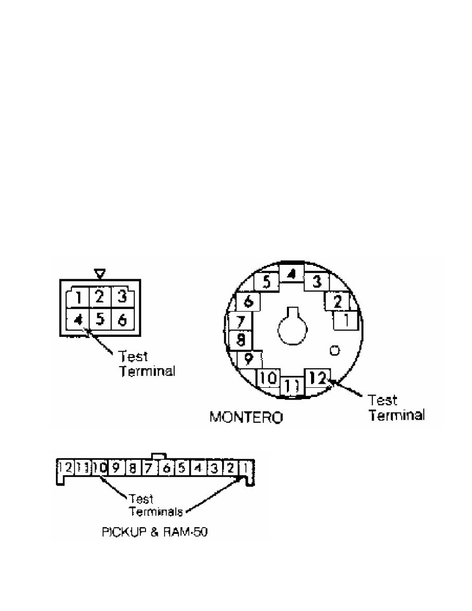
VEHICLE SPEED SENSOR
1) Vehicle Speed Sensor (VSS) is located in speedometer
assembly. Connect an ohmmeter between sensor terminals on back of
instrument panel. See Fig. 7 or 8.
2) Rotate speedometer cable. For each revolution of
speedometer cable, sensor should make and break continuity 4 times. If
ohmmeter reading does not fluctuate between continuity and no
continuity or if sensor does not make and break continuity 4 times for
each revolution, replace sensor.
Fig. 7: VSS Sensor Connector Term. ID (Montero)
Courtesy of Mitsubishi Motor Sales of America.
Fig. 8: VSS Sensor Connector Term. ID (P/U & Ram 50)
Courtesy of Mitsubishi Motor Sales of America.
MOTORS, RELAYS & SOLENOIDS
MOTORS
ISC Motor
See IDLE CONTROL SYSTEM.
RELAYS
NOTE: For internal wiring diagram of MPI control relay, see
appropriate L - WIRING DIAGRAMS article in the ENGINE
PERFORMANCE Section.
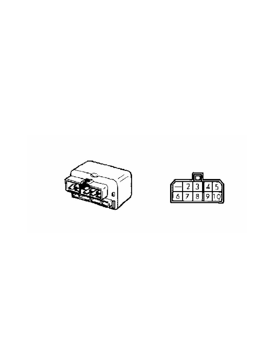
MPI Control Relay (Montero, Pickup 3.0L & Ram-50 3.0L)
1) MPI control relay is located near right kick panel. Check
for battery voltage at terminal No. 10 of relay connector. See Fig. 9.
If battery voltage is present, go to step 3). If battery voltage is
not present, check circuit between relay and battery, including
fusible link No. 1.
Fig. 9: MPI Control Relay Connector Term. ID (10 Pin)
Courtesy of Mitsubishi Motor Sales of America.
2) Apply battery voltage to terminal No. 10. Battery voltage
should not be present at terminals No. 4 and 5. Apply battery voltage
to terminal No. 10, and ground terminal No. 8. Battery voltage should
now be present at terminals No. 4 and 5.
3) Apply battery voltage to terminal No. 3. Battery voltage
should not be present at terminal No. 2. Apply battery voltage to
terminal No. 3, and ground terminal No. 7. Battery voltage should now
be present at terminal No. 2.
4) Apply battery voltage to terminal No. 9. Battery voltage
should not be present at terminal No. 2. Apply battery voltage to
terminal No. 9, and ground terminal No. 6. Battery voltage should now
be present at terminal No. 2. Replace relay if it does not test as
specified.
MPI Control Relay (Pickup 2.4L & Ram-50)
1) MPI control relay is located near right kick panel. Check
for battery voltage at terminal No. 4 of relay connector. See Fig. 10.
If battery voltage is present, go to step 3). If battery voltage is
Нет комментариевНе стесняйтесь поделиться с нами вашим ценным мнением.
Текст