Mitsubishi Montero (1991+). Manual — part 210
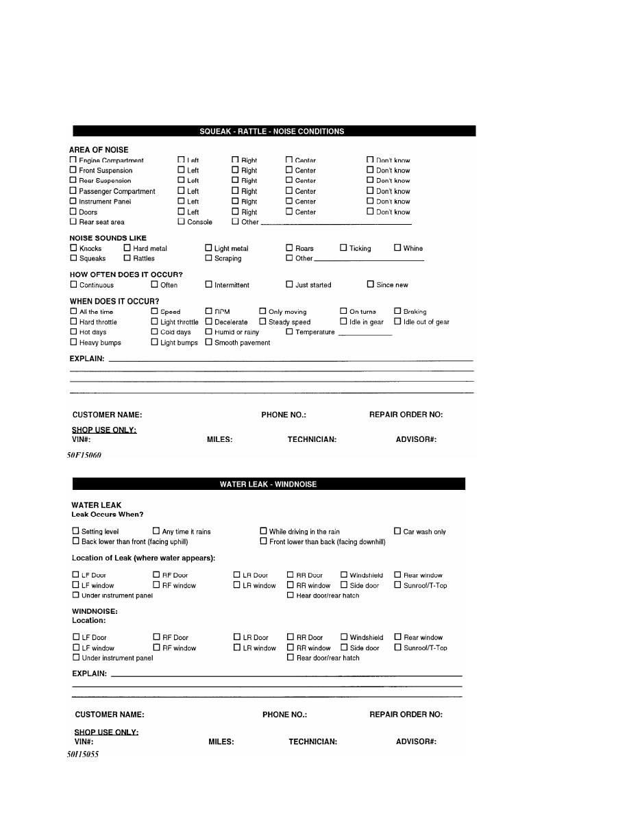
Fig. 11: Squeak, Rattle, & Noise Conditions
Fig. 12: Water Leak & Wind Noise
I - SYSTEM/COMPONENT TESTS
1991 Mitsubishi Montero
1991 ENGINE PERFORMANCE
System & Component Testing
Chrysler Motors: Ram-50
Mitsubishi: Montero, Pickup
INTRODUCTION
Before testing separate components or systems, perform
procedures in F - BASIC TESTING article in the ENGINE PERFORMANCE
Section. Since many computer controlled and monitored components set a
trouble code if they malfunction, also perform procedures in G - TESTS
W/CODES article in the ENGINE PERFORMANCE Section.
NOTE: Testing individual components does not isolate shorts or
opens. Perform all voltage tests with a Digital
Volt-Ohmmeter (DVOM) with a minimum 10-megohm input
impedance, unless stated otherwise in test procedure. Use
ohmmeter to isolate wiring harness shorts or opens.
COMPUTERIZED ENGINE CONTROLS
CONTROL UNIT
NOTE: To identify ECU power and ground circuits, see appropriate
L - WIRING DIAGRAMS article in the ENGINE PERFORMANCE
Section.
Ground Circuits
1) ECU is located near right kick panel. Turn ignition off.
Using an ohmmeter, check for continuity between ground and ECU
terminals No. 101 and 106. Resistance should be zero ohms. If
resistance is not zero ohms, repair open circuit between ECU connector
and ground.
2) Connect voltmeter negative lead to ground. Connect
positive lead to ECU ground terminals as in step 1). With vehicle
running, voltmeter should indicate less than one volt. If voltmeter
reading is greater than one volt, check for open, corrosion or loose
connection in ground circuit.
Power Circuits
ECU is located near right kick panel. Turn ignition on. Check
for battery voltage on ECU terminals No. 102 and 107. If battery
voltage is not present, check operation of MPI control relay. See
RELAYS under MOTORS, RELAYS & SOLENOIDS.
ENGINE SENSORS & SWITCHES
BAROMETRIC PRESSURE SENSOR
Sensor is a component part of airflow sensor assembly. See G
- TESTS W/CODES article in the ENGINE PERFORMANCE Section.
COOLANT TEMPERATURE SENSOR
1) Remove coolant temperature sensor located near thermostat
housing (2-wire connector). Place end of sensor in water with terminal
connector portion of sensor slightly above water.
2) Gradually heat water and read resistance values across
terminal connectors. See COOLANT TEMPERATURE SENSOR RESISTANCE table.
If resistance is not within specification, replace sensor.
COOLANT TEMPERATURE SENSOR RESISTANCE TABLE
Temperature
F (
C) Ohms
Montero & Pickup 3.0L
32 (0) . . . . . . . . 5900
68 (20) . . . . . . . 2500
104 (40) . . . . . . ... 2700
176 (80) . . . . . . . 300
All Others
32 (0) . . . . . . . . 5900
68 (20) . . . . . . . 2500
104 (40) . . . . . . ... 1100
176 (80) . . . . . . . 300
CRANK ANGLE SENSOR
See IGNITION SYSTEM.
DETONATION SENSOR
See IGNITION SYSTEM.
EGR TEMPERATURE SENSOR
California
See EXHAUST GAS RECIRCULATION (EGR) under EMISSION SYSTEMS &
SUB-SYSTEMS.
IDLE POSITION SWITCH
NOTE: Idle position switch is incorporated in idle speed control
motor assembly, motor position sensor or throttle position
sensor, depending upon vehicle application.
Pickup 2.4L & Ram-50 2.4L
1) Disconnect motor position sensor (MPS) connector. Connect
ohmmeter lead between ground and MPS connector terminal No. 4. See
Fig. 2.
2) With accelerator pedal pressed, no continuity should be
present. With accelerator pedal released, continuity should be
present. If switch continuity is not as specified, replace MPS.
Montero, Pickup 3.0L & Ram-50 3.0L
1) Disconnect throttle position sensor (TPS) connector.
Connect ohmmeter between TPS connector terminals No. 1 and 2. See
Fig. 6.
2) With accelerator pedal pressed, no continuity should be
present. With accelerator pedal released, continuity should be
present. If idle switch continuity is not as specified, replace TPS.
INHIBITOR SWITCH
Automatic Transmission
Switch is mounted to automatic transaxle, near shift lever
Нет комментариевНе стесняйтесь поделиться с нами вашим ценным мнением.
Текст