Mitsubishi Montero (1991+). Manual — part 213
not present, check circuit between relay and battery, including
fusible link No. 1.
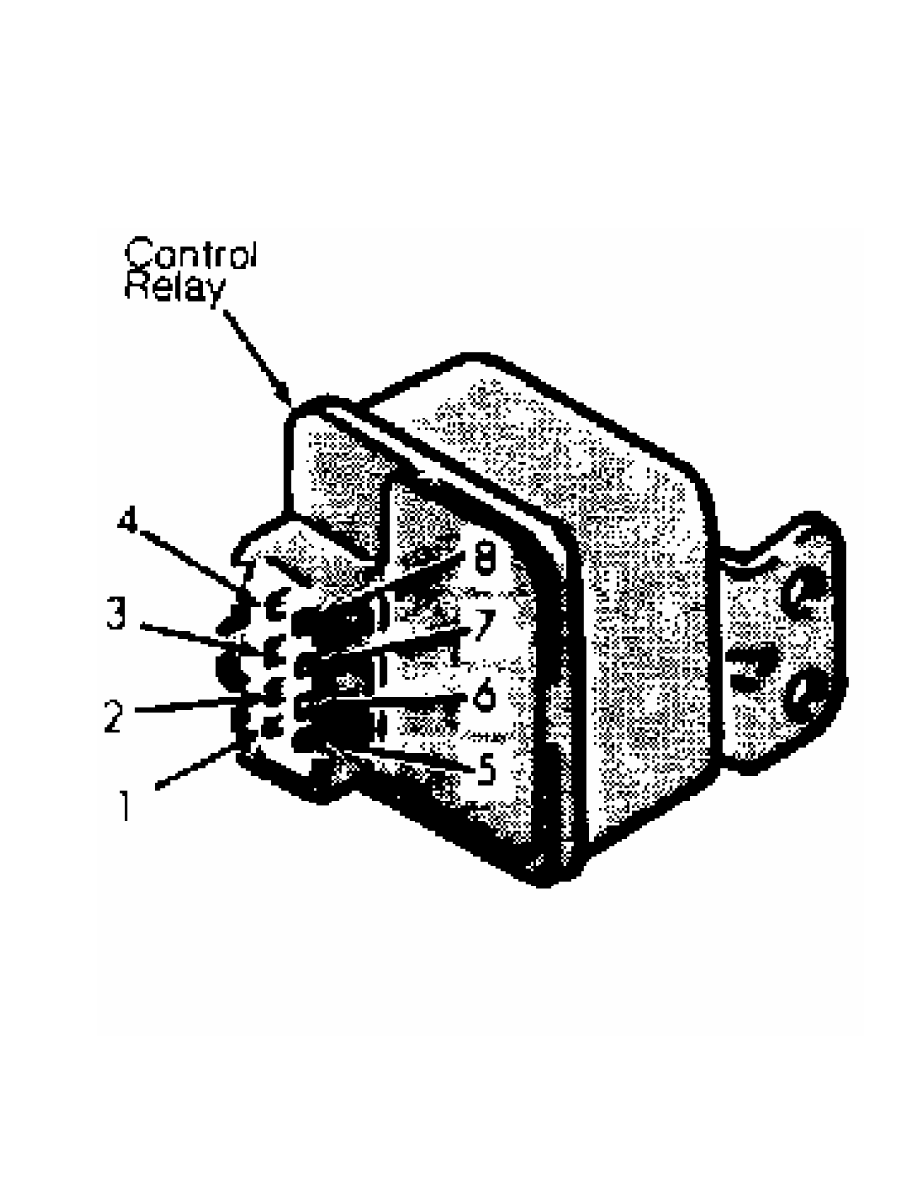
Fig. 10: MPI Control Relay Connector Term. ID (8 Pin)
Courtesy of Mitsubishi Motor Sales of America.
2) Disconnect wiring harness connector at relay. Remove
relay. Check continuity between terminals No. 1 and 4, terminals No. 2
and 4 and terminals No. 3 and 4. If there is no continuity, go to next
step. If there is continuity, replace relay.
3) Check diode operation between terminals No. 6 and 8. If
there is continuity in only one direction, go to next step. If there
is no continuity in either direction or if there is continuity in both
directions, replace relay.
4) Measure resistance between terminals No. 6 and 7. If
resistance is approximately 35 ohms, go to next step. If resistance is
not approximately 35 ohms, replace relay.
5) Measure resistance between terminals No. 2 and 5 and
between terminals No. 3 and 5. In both tests, if resistance is
approximately 95 ohms, go to next step. If resistance is not
approximately 95 ohms, replace relay.
6) Connect positive lead of 12-volt source to terminal No. 7
and negative lead to terminal No. 6. If there is continuity between
terminals No. 1 and 4, go to next step. If there is no continuity,
replace relay.
7) Connect positive lead of 12-volt source to terminal No. 5
and negative lead to terminal No. 2. If there is continuity between
terminals No. 1 and 4, go to next step. If there is no continuity,
replace relay.
8) Connect positive lead of 12-volt source to terminal No. 5
and negative lead to terminal No. 3. If there is continuity between
terminals No. 1 and 4, go to next step. If there is no continuity,
replace relay.
9) Connect positive lead of 12-volt source to terminal No. 8
and negative lead to terminal No. 6. If there is continuity between
terminals No. 3 and 4 and between terminals No. 2 and 4, relay is
okay. If there is no continuity, replace relay.
SOLENOIDS
Fuel Pressure Control Solenoid Valve
See FUEL DELIVERY under FUEL SYSTEM.
Fuel Injector Solenoids
See FUEL CONTROL under FUEL SYSTEM.
FUEL SYSTEM
FUEL DELIVERY
NOTE: For fuel system pressure testing, see F - BASIC TESTING
article in the ENGINE PERFORMANCE Section.
FUEL CONTROL
Fuel Injectors
1) Using a stethoscope, check operating sound of injector(s)
during engine cranking or idling. If clicking sound is heard,
injectors are okay. If clicking sound is not heard at each injector,
go to step 2).
2) Disconnect injector electrical connector. Measure
resistance between injector connector terminals. At 68
F (20
C), if
resistance is not 13-16 ohms, replace injector.
3) If resistance is within specification, check injector
wiring circuit for open or short to ground. If wiring circuit tests
okay, replace injector.
IDLE CONTROL SYSTEM
NOTE: ISC motor adjusts throttle plate angle to regulate idle air
by-pass volume.
IDLE SPEED CONTROL (ISC) MOTOR OPERATION TEST
CAUTION: DO NOT apply more than 6 volts to ISC motor.
Pickup 2.4L & Ram-50 2.4L
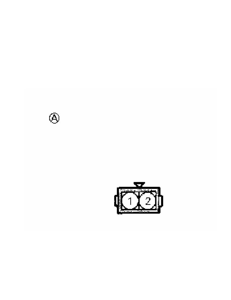
Connect 6-volt DC source across terminals No. 1 and 2 of ISC
motor connector. See Fig. 11. Reverse leads of 6-volt source. If motor
does not operate in both directions, replace ISC motor assembly.
Fig. 11: ISC Motor Connector Term. ID (2 Pin)
Courtesy of Mitsubishi Motor Sales of America.
Montero, Pickup 3.0L & Ram-50 3.0L
1) Remove throttle body from intake plenum. Remove ISC motor
from throttle body. Apply 6-volt source parallel to terminals No. 2
and 5 of ISC motor connector. See Fig. 12.

Fig. 12: ISC Motor Connector Term. ID (6 Pin)
Courtesy of Mitsubishi Motor Sales of America.
2) Apply source ground lead to ISC motor connector terminals
No. 3 and 6. Note slight movement of ISC motor plunger. Remove ground
leads from terminals No. 3 and 6.
3) Apply and remove source ground at terminals No. 1 and 6, 1
and 4, 3 and 4, and 3 and 6. Note slight movement of ISC motor plunger
during each phase of test.
4) Beginning at terminal No. 6, reverse grounding sequence
following same procedure specified in step 2). If motor does not
operate when grounding any of specified terminals, replace ISC motor.
IDLE SPEED CONTROL (ISC) MOTOR RESISTANCE TEST
Pickup 2.4L & Ram-50 2.4L
Disconnect ISC motor connector. Connect ohmmeter between
terminals No. 1 and 2 of ISC motor connector. See Fig. 11. If
resistance is not 5-35 ohms at 68
F (20
C), replace ISC motor
assembly.
Montero, Pickup 3.0L & Ram-50 3.0L
Measure resistance between terminals No. 1 and 2, 2 and 3, 4
and 5, and 5 and 6 of ISC motor connector. See Fig. 12. In each case,
if resistance is not 28-33 ohms at 68
F (20
C), replace ISC motor
Нет комментариевНе стесняйтесь поделиться с нами вашим ценным мнением.
Текст