Mitsubishi Montero (1991+). Manual — part 19
A/C-HEATER SYSTEM - MANUAL
1991 Mitsubishi Montero
1991 MANUAL A/C-HEATER SYSTEMS
Chrysler Motors, Mitsubishi
Chrysler Motors: Colt Vista, Ram-50
Mitsubishi: Montero, Pickup
* PLEASE READ THIS FIRST *
CAUTION: When discharging air conditioning system, use only approved
refrigerant recovery/recycling equipment. Make every attempt
to avoid discharging refrigerant into the atmosphere.
A/C SYSTEM SPECIFICATIONS
SPECIFICATIONS TABLE
Compressor Type
Colt Vista & Montero . . . . . Nippondenso 10-Cyl.
Pickup & Ram-50 . . . . . . . ... Sanden Scroll
Compressor Belt Deflection
Colt Vista . . . . . . . 11/32-7/16" (8-11 mm)
Montero . . . . . . . . 21/64-3/8" (8.5-9.5 mm)
Pickup & Ram-50 . . . . . 21/64-25/64" (8.5-10 mm)
Compressor Oil Capacity
Colt Vista & Montero . . . . . . . ... 2.7 ozs.
Pickup & Ram-50 . . . . . . . . . 5.0 ozs.
Refrigerant (R-12) Capacity
Colt Vista & Montero . . . . . . . . 32 ozs.
Pickup & Ram-50 . . . . . . . . . . 30 ozs.
System Operating Pressures (1)
Colt Vista, Pickup & Ram-50
High Side . . . . . 130-220 psi (9.1-15.5 kg/cm
)
Low Side . . . . . . 20-26 psi (1.4-1.8 kg/cm
)
Montero
Dual Unit
High Side . . . . .. 142-199 psi (9.9-14.0 kg/cm
)
Low Side . . . . . .. 16-30 psi (1.1-2.1 kg/cm
)
Single Unit
High Side . . . . ... 102-142 psi (7.1-9.9 kg/cm
)
Low Side . . . . . .. 18-32 psi (1.3-2.2 kg/cm
)
(1) - With ambient temperature at least 80
F (27
C).
DESCRIPTION
Slight variations exist among the manual A/C-heater systems
used. Either Sanden Scroll or Nippondenso 10-cylinder compressor is
used. Cycling of the compressor clutch is controlled by switches which
monitor temperatures and pressures.
Compressors will only operate within the normal operating
temperatures and pressures set for each model. An electric condenser
fan operates whenever A/C system is operating. System components used
vary depending upon model. Most systems include an A/C compressor
control unit, fan switch, evaporator, temperature sensor, high and low
(or dual) pressure switch, engine coolant temperature switch,
compressor, condenser, receiver-drier and various pipes and hoses.
OPERATION
A/C SWITCH
The A/C switch is located in the lower, center section of
control panel. See Fig. 1. When switch is pushed, air conditioning
will operate if blower motor control lever is in a position other than
OFF.
When activated, the A/C button/switch allows the A/C
compressor clutch to engage and operate the compressor. On some
models, a light on the button will glow when button/switch is
activated.
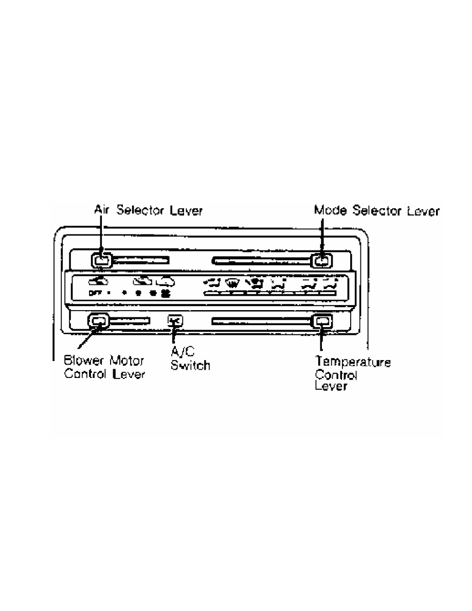
Fig. 1: A/C Switch & Control Panel
Courtesy of Mitsubishi Motor Sales of America.
AIR SELECTOR LEVER
The air selector lever is located in the upper, left corner
of control panel and moves horizontally to select the source of air
needed inside of passenger compartment. Lever moves from OFF position
on the left to the outside air mode, to the mixture of both outside
and inside air mode, and to the recirculation mode on the right. Lever
should normally be set in the recirculation mode for maximum A/C
cooling.
BLOWER MOTOR CONTROL LEVER
Blower motor control lever is located on the lower, left
corner of control panel and moves horizontally to select blower motor
speeds. As lever is moved from far left or OFF position, increasing
speeds of blower operation are selected. In order for A/C system to
operate, blower motor control lever MUST be in a position other than
OFF.
MODE SELECTOR LEVER
Mode selector lever is located in upper right corner of
control panel. Either 2 or 6 modes are available to achieve desired
distribution of air from various outlets.
On all models, air is directed to windshield and side
windows and comes out from the panel outlets when mode selector lever
is positioned to the far left. When lever is moved one detent to the
right, air is directed to windshield and side windows simultaneously.
On 6-mode models, air is directed to floor area, windshield,
and side windows when lever is moved 2 detents to the right. When
lever is moved 3 detents to the right, air is directed to floor area.
When lever is moved to the second to last detent on control panel, air
is directed to floor area and panel outlets. When lever is in the far
right position, air will be directed to panel outlets only.
TEMPERATURE CONTROL LEVER
The temperature control lever operates blend-air door in the
heater/air conditioning unit, mixing cooled and heated air so the
selected air temperature can be obtained. The system will provide
cooled air when A/C switch is in ON position and blower motor is in
any position other than OFF. The temperature control lever should be
in the far left (maximum cooling) side of temperature selection scale
when maximum A/C cooling is desired.
DUAL PRESSURE SWITCH
The dual pressure switch, located in the refrigerant line
near condenser, is wired in series with compressor clutch. Whenever
system pressures drop below or increase above the control point of the
switch, power supplied to compressor will be cut and compressor
activity will cease until pressures are back to within operating
ranges.
ENGINE COOLANT TEMPERATURE SWITCH
The engine coolant temperature switch, located on thermostat
housing, is wired in series with compressor clutch. When coolant
temperature is greater than switch control temperature, power to
compressor is cut and compressor is turned off until temperature
returns to operating range.
EVAPORATOR THERMISTOR
The evaporator thermistor, attached to evaporator fins, is
wired in series with compressor clutch and prevents evaporator
freezing. Power to compressor clutch is cut if control temperature is
exceeded, allowing evaporator to thaw. When temperature returns to
operating range, thermistor allows power to compressor clutch.
FUSIBLE PLUG
A fusible plug, located on receiver-drier, melts and allows
refrigerant to escape when ambient temperatures in engine compartment
reach 221
F (105
C). Once fusible plug has blown, it cannot be reused
and must be replaced.
HIGH PRESSURE SWITCH
The high pressure switch, installed in refrigerant line, is
wired in series with compressor clutch. When refrigerant pressures
rise above switch control pressure point, power to compressor clutch
is cut. The high pressure switch may also be activated when airflow
through condenser is blocked or when system is overcharged.
HIGH/LOW PRESSURE CUT-OFF SWITCH
The High/Low Pressure Cut-Off (HLPCO) switch, located on
refrigerant line, is wired in series with compressor clutch. Switch
cuts off power to compressor clutch when refrigerant pressures are
above or below switch control point. When pressure returns to normal
operating range, compressor clutch operation resumes.
LOW PRESSURE SWITCH
The low pressure switch, located in receiver-drier, is wired
in series with compressor clutch. When refrigerant pressure drops
below switch control point (usually due to leak in system), power to
compressor clutch is cut.
REFRIGERANT TEMPERATURE SWITCH
The refrigerant temperature switch, located on rear of
compressor, detects refrigerant temperature discharged from
compressor. A/C Control Unit (ACCU) uses this information to control
compressor clutch cycling.
ADJUSTMENTS
NOTE: For adjustment procedures not covered in this article, see
appropriate HEATER SYSTEM article in the AIR CONDITIONING &
HEAT Section.
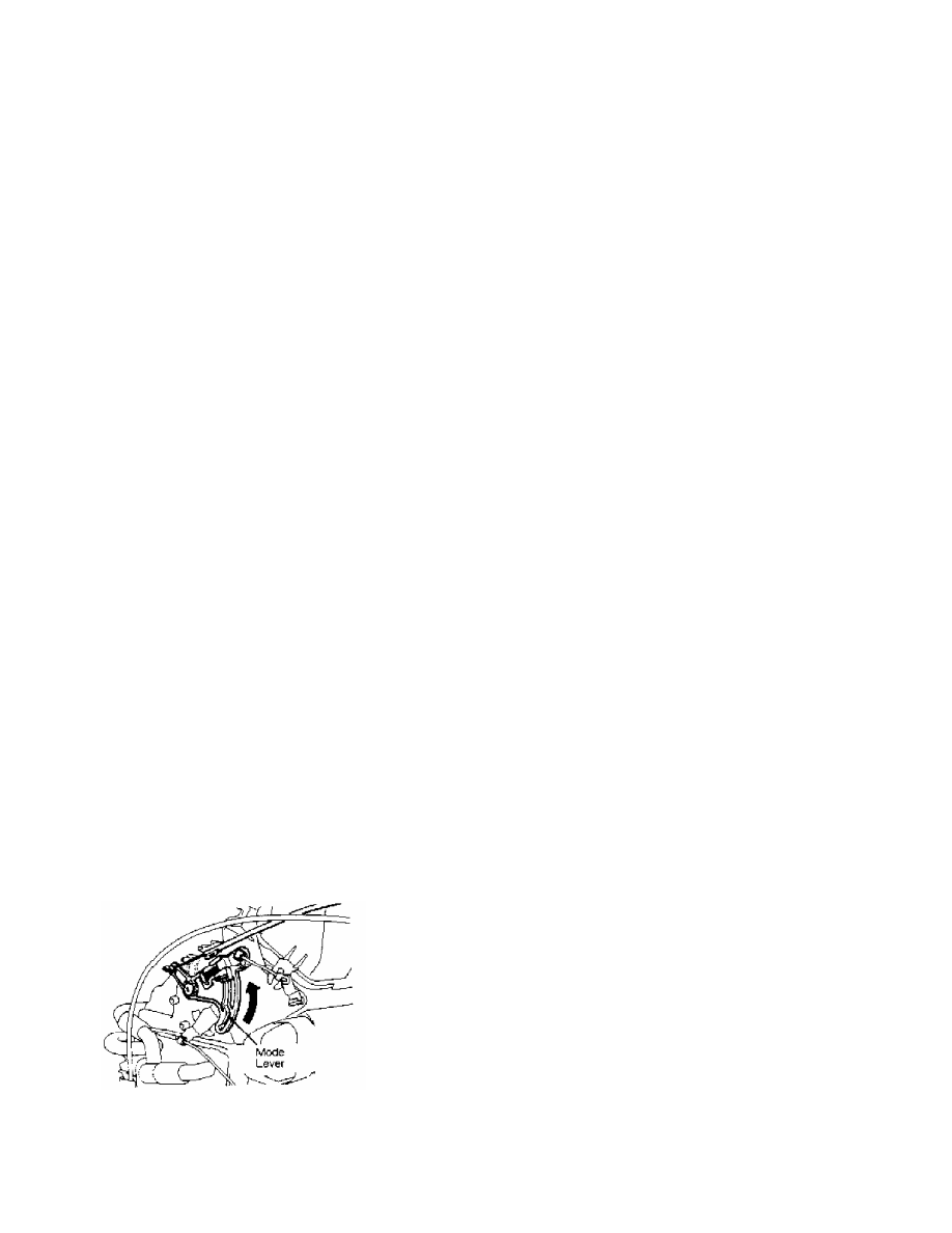
MODE CONTROL CABLE
Montero
Move mode selector lever to far left (DEF) position. Move
mode door lever upward in direction indicated by arrow. See Fig. 2.
Connect inner wire to lever, and secure outer housing using clip.
Operate mode control knob to ensure proper operation.
Fig. 2: Adjusting Mode Selection Cable (Montero)
Courtesy of Mitsubishi Motor Sales of America.
TEMPERATURE CONTROL CABLE
Нет комментариевНе стесняйтесь поделиться с нами вашим ценным мнением.
Текст