Mitsubishi Montero (1991+). Manual — part 20

Montero
1) Move temperature selector lever to far left position.
Remove heater control valve cover. Disconnect heater control valve
wire from blend door lever. Push heater control valve inward (closed).
2) Move blend door lever downward in direction indicated by
arrow. See Fig. 3. Connect inner wire to lever, and secure outer
housing using clip. Adjust heater control valve wire so valve is fully
closed. Operate mode control knob to ensure proper operation.
Reinstall heater control valve cover.
Fig. 3: Adjusting Temperature Selection Cable (Montero)
Courtesy of Mitsubishi Motor Sales of America.
TROUBLE SHOOTING
AIR NOT COOL
1) Ensure compressor clutch is operating. If compressor
clutch is not operating, check fuses and relay. Check A/C switch.
Check high and low pressure switches or dual pressure switch. Check
thermistor, thermo relay or Electronic Cycling Clutch Switch (ECCS).
Check blower switch and relay. Check A/C compressor clutch coil.
2) Ensure system is properly charged with correct amount of
refrigerant. Add refrigerant or evacuate and recharge system as
necessary. Ensure receiver-drier is not clogged. Check compressor belt
for proper tension. Check for clogged expansion valve. Check
compressor operation. Repair or replace compressor as necessary.
INSUFFICIENT AIRFLOW
Check for air leakage at air duct joint. Check for frost on
evaporator. Ensure blower motor is operating properly. Check for
obstructed air intake.
INSUFFICIENT COOLING
Ensure system is properly charged with correct amount of
refrigerant and free of air and moisture. Add refrigerant or evacuate
and recharge system as necessary. Ensure receiver-drier is not
clogged. Ensure sufficient airflow through condenser exists. Check
compressor belt for proper tension. Check compressor operation. Repair
or replace compressor as necessary. Check for clogged expansion valve.
Replace expansion valve as necessary.
INTERMITTENT COOL AIR
Check for air or moisture in system. Evacuate and recharge
system as necessary. Check for expansion valve malfunction. Replace
expansion valve if necessary. Check compressor belt for proper
tension.
TESTING
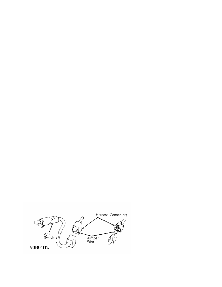
A/C SWITCH
1) Disconnect A/C switch harness connector. Using appropriate
wiring diagram as a guide, jumper appropriate terminals of A/C switch
wiring harness connector. See Fig. 4.
2) Turn blower on and momentarily turn ignition on without
starting engine. Listen for compressor clutch engagement. If
compressor clutch does not engage, check fuse and other components
wired in series with compressor clutch.
Fig. 4: A/C Switch Connector ID
Courtesy of Mitsubishi Motor Sales of America.
AIR THERMO & AIR INLET SENSORS
1) Disconnect sensor connector at evaporator case. Using an
ohmmeter, measure continuity between sensor terminals. See AIR THERMO
& AIR INLET SENSORS SPECIFICATIONS table.
2) If resistance is not within specifications, sensor is
faulty and must be replaced. If resistance is within specifications
and all other components are okay, replace A/C compressor control unit
(if equipped).
AIR THERMO & AIR INLET SENSORS SPECIFICATIONS TABLE
Sensor Temperature Ohms
Air Thermo Sensor
32
F (0
C) . . . . . . . . .. 11,400
50
F (10
C) . . . . . . . . ... 7320
68
F (20
C) . . . . . . . . ... 4860
86
F (30
C) . . . . . . . . ... 3310
104
F (40
C) . . . . . . . . .. 2320
Air Inlet Sensor
32
F (0
C) . . . . . . . . . 3310
50
F (10
C) . . . . . . . . ... 2000
68
F (20
C) . . . . . . . . ... 1250
86
F (30
C) . . . . . . . . . 810
104
F (40
C) . . . . . . . . . 530
BLOWER RESISTOR
Disconnect blower resistor connector. Using an ohmmeter,
measure resistance between terminals indicated in BLOWER RESISTOR
RESISTANCE table. See Fig. 5.
BLOWER RESISTOR RESISTANCE TABLE
Terminal Ohms
Colt Vista
1 & 2 . . . . . . . . Approx. 1.22
1 & 3 . . . . . . . . Approx. 0.41
1 & 4 . . . . . . . . Approx. 2.65
1 & 5 . . . . . . . . ... Approx. 0
Montero (Front)
1 & 2 . . . . . . . . Approx. 1.22
1 & 3 . . . . . . . . Approx. 0.41
1 & 4 . . . . . . . . Approx. 2.25
1 & 5 . . . . . . . . ... Approx. 0
Montero (Rear)
2 & 4 . . . . . . . . . Approx. 0.5
1 & 4 . . . . . . . . . Approx. 1.8
3 & 4 . . . . . . . . . Approx. 3.3
Pickup & Ram-50
1 & 2 . . . . . . . . Approx. 1.19
1 & 3 . . . . . . . . Approx. 0.50
1 & 4 . . . . . . . . Approx. 2.33
1 & 5 . . . . . . . . ... Approx. 0
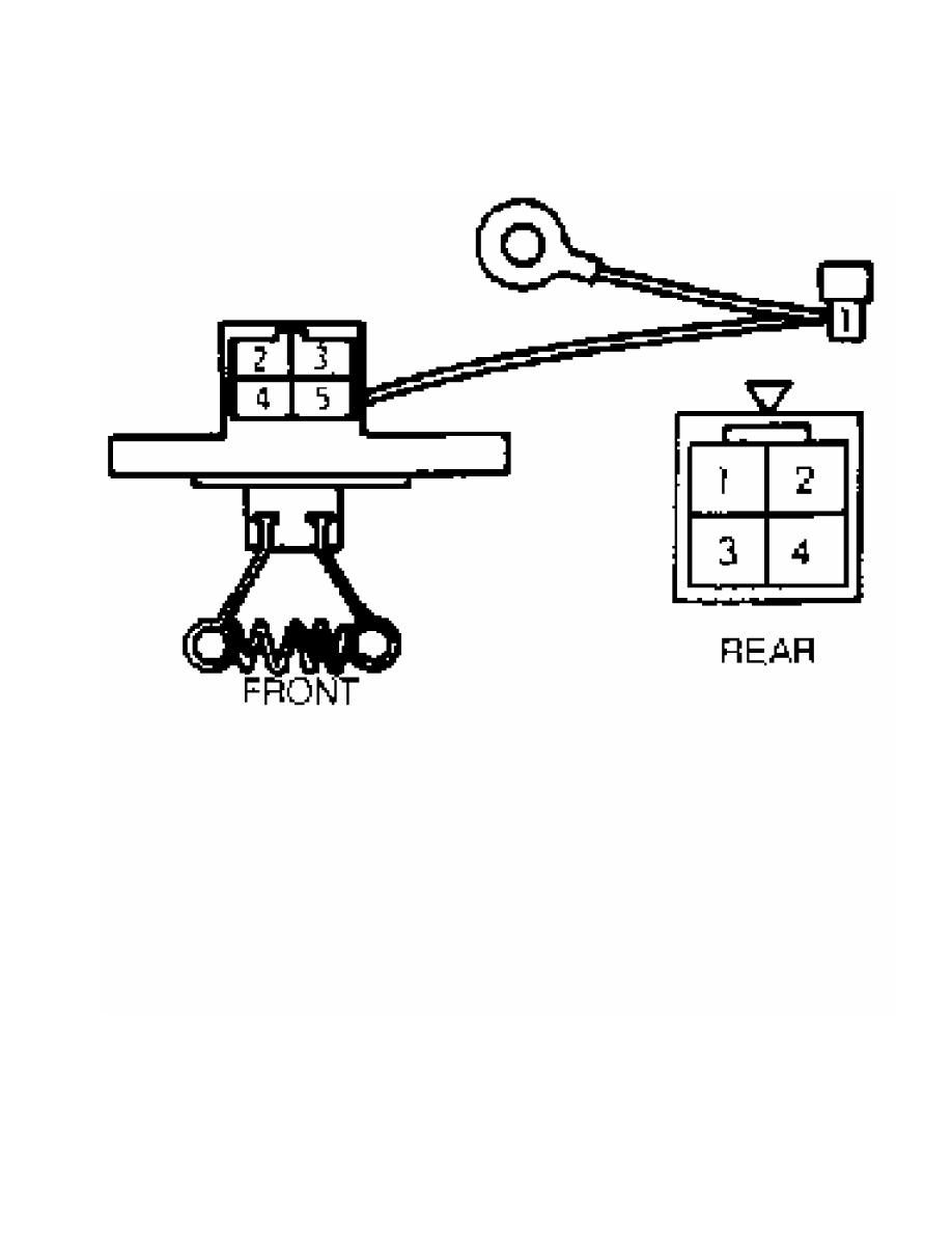
Fig. 5: Testing Blower Resistor
Courtesy of Mitsubishi Motor Sales of America.
BLOWER SWITCH
With blower switch in position indicated in BLOWER SWITCH
CONTINUITY TEST table, ensure continuity exists between terminals
listed. See Fig. 6 or 7.
BLOWER SWITCH CONTINUITY TEST TABLE
Нет комментариевНе стесняйтесь поделиться с нами вашим ценным мнением.
Текст