Mitsubishi Montero (1991+). Manual — part 328

subtracted by the width measured at the front of the tires at about
spindle height. A positive figure would indicate toe-in and a negative
figure would indicate toe-out. If the distance between the front and
rear of the tires is the same, toe measurement would be zero. To
adjust:
1) Measure toe-in with front wheels in straight ahead
position and steering wheel centered. To adjust toe-in, loosen clamps
and turn adjusting sleeve or adjustable end on right and left tie
rods. See Figs. 2 and 5.
2) Turn equally and in opposite directions to maintain
steering wheel in centered position. Face of tie rod end must be
parallel with machined surface of steering rod end to prevent binding.
3) When tightening clamps, make certain that clamp bolts are
positioned so there will be no interference with other parts
throughout the entire travel of linkage.
Fig. 5: Wheel Toe-In (Dimension A Less Dimension B)
TOE-OUT ON TURNS
1) Toe-out on turns (turning radius) is a check for bent or
damaged parts, and not a service adjustment. With caster, camber, and
toe-in properly adjusted, check toe-out with weight of vehicle on
wheels.
2) Use a full floating turntable under each wheel, repeating
test with each wheel positioned for right and left turns. Incorrect
toe-out generally indicates a bent steering arm. Replace arm, if
necessary, and recheck wheel alignment.
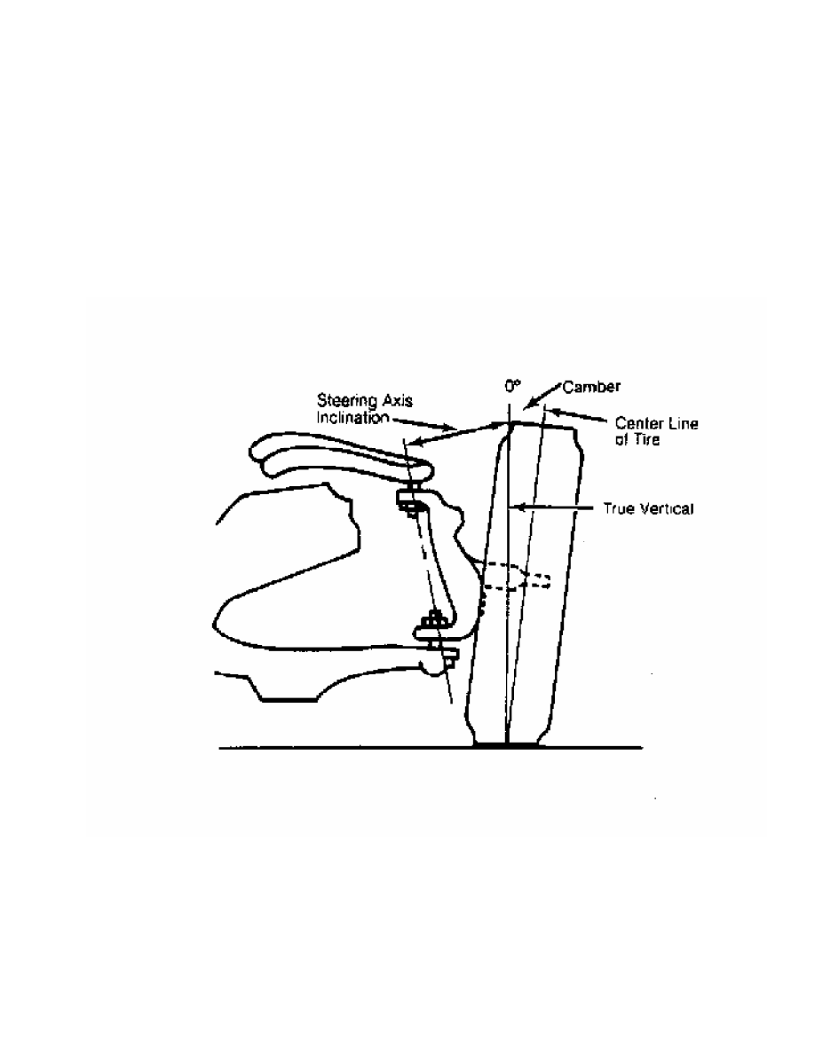
STEERING AXIS INCLINATION
1) Steering axis inclination is a check for bent or damaged
parts, and not a service adjustment. Vehicle must be level and camber
should be properly adjusted. See Fig. 6.
2) If camber cannot be brought within limits and steering
axis inclination is correct, steering knuckle is bent. If camber and
steering axis inclination are both incorrect by approximately the same
amount, the upper and lower control arms are bent.
Fig. 6: Checking Steering Axis Inclination
WIPER/WASHER SYSTEM
1991 Mitsubishi Montero
1991 ACCESSORIES & SAFETY EQUIPMENT
Chrysler Motors/Mitsubishi Wiper/Washer Systems
Dodge; Ram-50
Mitsubishi: Montero, Pickup
DESCRIPTION & OPERATION
All models are equipped with a 2-speed wiper motor with an
optional intermittent wiper feature. Some models are equipped with a
rear wiper/washer.
ADJUSTMENTS
FRONT WIPER ARM ADJUSTMENT
Ensure wiper motor is in park position. Position wiper arm
and blade assembly so tip of blade is specified distance above front
window trim. See FRONT WIPER ADJUSTMENT SPECIFICATIONS table.
FRONT WIPER ADJUSTMENT SPECIFICATIONS TABLE
Model Driver Side: In. (mm) Passenger Side: In. (mm)
Montero . . . 1.5-1.9 (37-47) . . . . 1.5-1.9 (37-47)
Pickup & Ram-50 . . .6 (15) . . . . . . 1.0 (25)
REAR WIPER ARM ADJUSTMENT
NOTE: Pickup and Ram-50 are not equipped with rear wipers.
Ensure wiper motor is in park position. Position wiper arm
and blade assembly so tip of blade is specified distance from edge of
window. See REAR WIPER ADJUSTMENT SPECIFICATIONS table.
REAR WIPER ADJUSTMENT SPECIFICATIONS TABLE
Model In. (mm)
Montero . . . . . . . . . ... ( 2) *
(2) - Blade parallel with lower edge of window.
TESTING
FRONT WIPER MOTOR
Checking Wiper Motor Operation ( Montero, Pickup & Ram-50)
Disconnect wiring connector from wiper motor. Connect battery
voltage to appropriate wiper motor terminal, and ground other
terminal. See WIPER MOTOR OPERATION CHECK table. See Fig. 1. Ensure
wiper motor operates in both low and high speeds.
WIPER MOTOR OPERATION CHECK TABLE
Model & Ground Apply Voltage
Application Terminal No. To Terminal No.
Low Speed Operation
Montero . . . . . .. 3 . . . . . . . . 1
Pickup & Ram-50 . . . .. 1 . . . . . . . . 3
High Speed Operation
Montero . . . . . .. 4 . . . . . . . . 1
Pickup & Ram-50 . . . .. 2 . . . . . . . . 3
Fig. 1: Front Wiper Motor Terminal ID (Montero, Pickup & Ram-50)
Courtesy of Mitsubishi Motor Sales of America.
Checking Automatic Stop (Montero, Pickup & Ram-50)
1)Operate wiper motor at low speed. See CHECKING WIPER MOTOR
OPERATION. Disconnect battery voltage to stop motor in any position
except park.
2) Using a jumper wire, connect 2 terminals indicated. See
AUTOMATIC STOP CHECK table. See Fig. 1. Connect 12 volts to terminal
indicated in table, and ground wiper motor bracket. Ensure motor parks
wiper arm.
AUTOMATIC STOP CHECK TABLE
Model Jumper Pin Nos. Apply Voltage To Pin Nos.
Montero . . . . 3 & 2 . . . . . . . . . 1
Pickup & Ram-50 . . 1 & 4 . . . . . . . . . 3
FRONT WIPER RELAY
NOTE: On Pickup, Ram-50,intermittent wiper relay is incorporated
into wiper switch. See STEERING COLUMN SWITCHES article in
the ACCESSORIES/SAFETY EQUIP Section. Precis does not have a
front wiper relay.
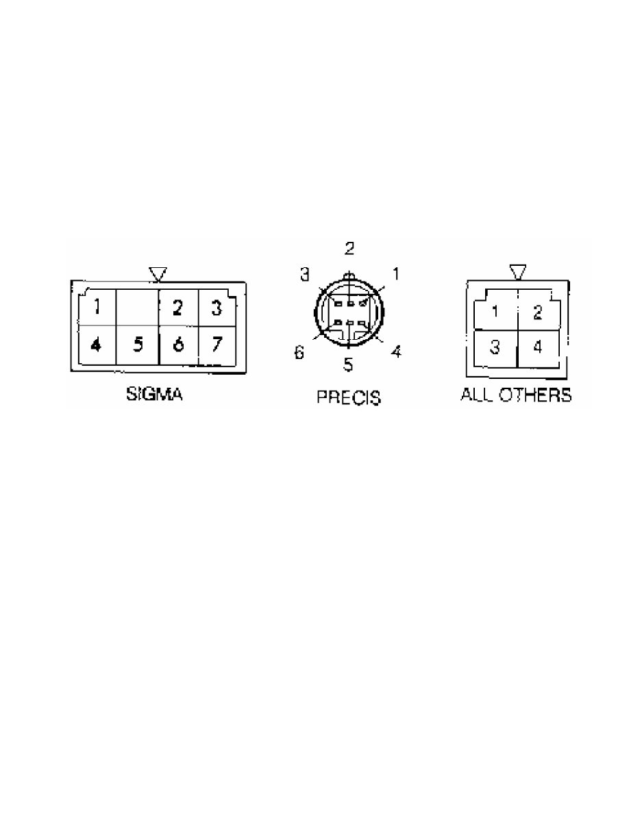
Continuity Check (Montero)
Remove relay. Relay is located behind driver’s kick panel.
Make sure continuity is present between terminals No. 2 and 5. See
Fig. 2.
Нет комментариевНе стесняйтесь поделиться с нами вашим ценным мнением.
Текст