Mitsubishi Montero (1991+). Manual — part 327
Front . . . . . 1/32 (1) . -1/16 to 5/32 (-2 to 4)
Rear . . . . . ... 0 (0) . . . . . ... . .
Toe-In (Degrees)
Front . . . . . .. 1/16 . . . . . -1/8 to 5/16
Rear . . . . . . . 0 . . . . . . . . .
Toe-Out on Turns (Degrees)
Inner . . . . . . 37 3/8 . . . . . ... . .
Outer . . . . . . 31 1/2 . . . . . ... . .
WHEEL ALIGNMENT SPECIFICATIONS TABLE (STEALTH & 3000GT)
Application Preferred Range
Front Wheel Drive
Camber (Degrees)
Front & Rear . . . ... 0 . . . . ... -1/2 to 1/2
Caster (Degrees) . . .. 3 29/32 . . . 3 13/32 to 4 29/32
Toe-In (In. (mm))
Front . . . . . 0 (0) . ... -1/8 to 1/8 (-3 to 3)
Rear . . . . . . 0 (0) . . -3/32 to 3/32 (-2 to 2)
Toe-In (Degrees)
Front . . . . . .. 0 . . . . ... -1/4 to 1/4
Rear . . . . . ... 0 . . . . . -3/16 to 3/16
Toe-Out on Turns (Degrees)
Inner . . . . ... 33 3/4 . . . . . ... . .
Outer . . . . .. 28 11/32 . . . . . .. . .
All Wheel Drive
Camber (Degrees)
Front . . . . . .. 0 . . . . ... -1/2 to 1/2
Rear . . . . . . -5/32 . . . . -21/32 to 11/32
Caster (Degrees) . . .. 3 29/32 . . . 3 13/32 to 4 29/32
Toe-In (In. (mm))
Front . . . . . 0 (0) . ... -1/8 to 1/8 (-3 to 3)
Rear . . . . . . 0 (0) . . -3/32 to 3/32 (-2 to 2)
Toe-In (Degrees)
Front . . . . . . 0 . . . . ... -1/4 to 1/4
Rear . . . . . .. 0 . . . . . -3/16 to 3/16
Toe-Out on Turns (Degrees)
Inner . . . . .. 33 3/4 . . . . . ... . .
Outer . . . . . 28 11/32 . . . . . .. . .
WHEEL ALIGNMENT THEORY/OPERATION
1991 Mitsubishi Montero
GENERAL INFORMATION
Wheel Alignment Theory & Operation
ALL MODELS
* PLEASE READ THIS FIRST *
NOTE: This article is intended for general information purposes
only. This information may not apply to all makes and models.
PRE-ALIGNMENT INSTRUCTIONS
GENERAL ALIGNMENT CHECKS
Before adjusting wheel alignment, check the following:
* Each axle uses tires of same construction and tread style,
equal in tread wear and overall diameter. Verify that radial
and axial runout is not excessive. Inflation should be at
manufacturer’s specifications.
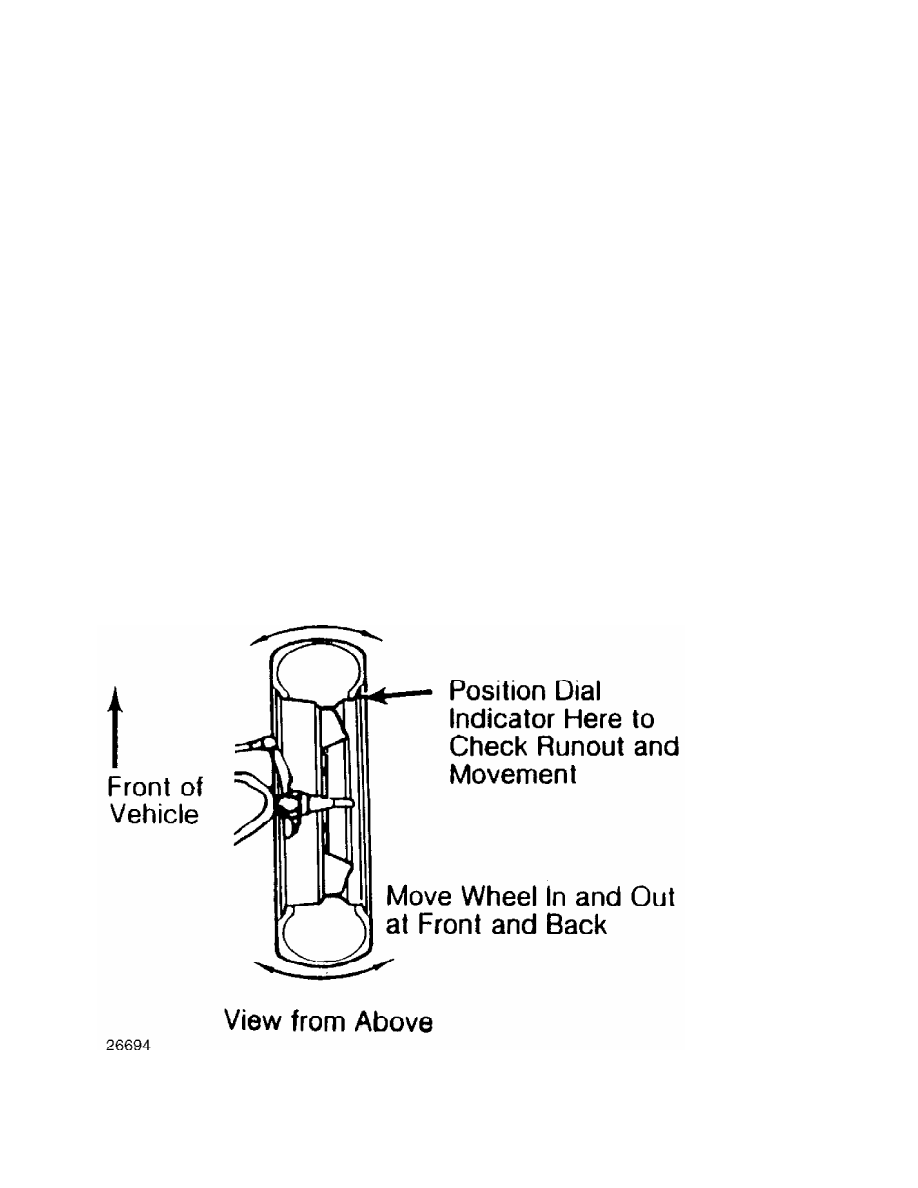
* Steering linkage and suspension must not have excessive play.
Check for wear in tie rod ends and ball joints. Springs must
not be sagging. Control arm and strut rod bushings must not
have excessive play. See Fig. 1.
Fig. 1: Checking Steering Linkage
* Vehicle must be on level floor with full fuel tank, no
passenger load, spare tire in place and no load in trunk.
Bounce front and rear end of vehicle several times. Confirm
vehicle is at normal riding height.
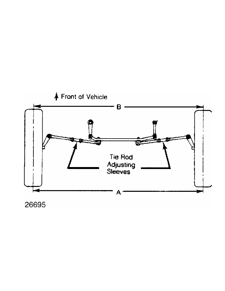
* Steering wheel must be centered with wheels in straight ahead
position. If required, shorten one tie rod adjusting sleeve
and lengthen opposite sleeve (equal amount of turns). See
Fig. 2.
* Wheel bearings should have the correct preload and lug nuts
must be tightened to manufacturer’s specifications. Adjust
camber, caster and toe-in using this sequence. Follow
instructions of the alignment equipment manufacturer.
CAUTION: Do not attempt to correct alignment by straightening parts.
Damaged parts must be replaced.
Fig. 2: Adjusting Tie Rod Sleeves (Top View)
CAMBER
1) Camber is the tilting of the wheel, outward at either top
or bottom, as viewed from front of vehicle. See Fig. 3.
2) When wheels tilts outward at the top (from centerline of
vehicle), camber is positive. When wheels tilt inward at top, camber
is negative. Amount of tilt is measured in degrees from vertical.
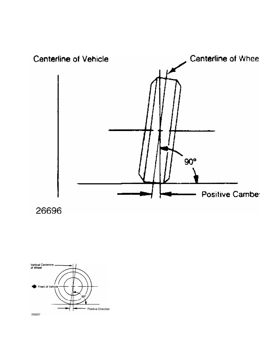
Fig. 3: Determining Camber Angle
CASTER
1) Caster is tilting of front steering axis either forward or
backward from vertical, as viewed from side of vehicle. See Fig. 4.
2) When axis is tilted backward from vertical, caster is
positive. This creates a trailing action on front wheels. When axis is
tilted forward, caster is negative, causing a leading action on front
wheels.
Fig. 4: Determining Caster Angle
TOE-IN ADJUSTMENT
Toe-in is the width measured at the rear of the tires
Нет комментариевНе стесняйтесь поделиться с нами вашим ценным мнением.
Текст