Mitsubishi Eclipse / Eclipse Spyder (2000-2002). Service and repair manual — part 257
MULTIPORT FUEL INJECTION (MFI) DIAGNOSIS
TSB Revision
MULTIPORT FUEL INJECTION (MFI) <3.0L ENGINE>
13B-227
DTC P0202: Injector Circuit Malfunction
−
Cylinder 2 DTC P0204: Injector Circuit Malfunction
−
Cylinder 4 DTC P0206: Injector Circuit Malfunction
−
Cylinder 6
AK000699
1 2
3
RED-
WHITE
YELLO
W
-RED
GREEN-YELLO
W
LIGHT GREEN
RED
RED
RED
RED-
WHITE
RED-
WHITE
4
RED
25
9
A-21X
2
ENGINE CONTROL
MODULE(ECM)<M/T>
OR
POWERTRAIN CONTROL
MODULE(PCM)<A/T>
1
1
1
2
2
2
INJECTOR
NO.2
B-02
B-06
B-25
INJECTOR
NO.4
INJECTOR
NO.6
MFI
RELAY
BATTERY
1
2
3
4
C-51<M/T>,C-52<A/T>
(MU803784)
2
3 4
5 6
7 8
9
11 12 13 14 15 16 17 18 19 20
30
21 22 23
24 25
26 27 28 29
3132 33
34 35
1
10
2
1
2
1
2
1
MULTIPORT FUEL INJECTION (MFI) DIAGNOSIS
TSB Revision
MULTIPORT FUEL INJECTION (MFI) <3.0L ENGINE>
13B-228
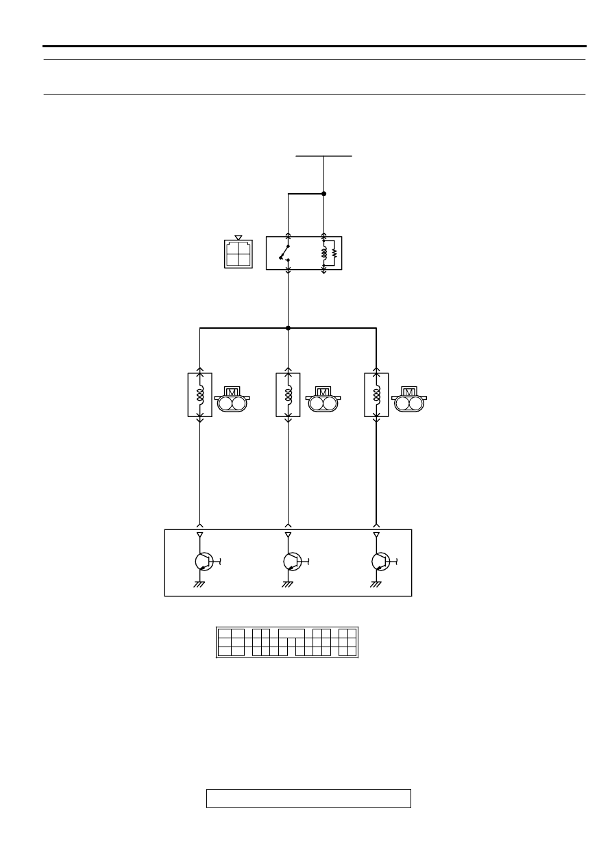
CIRCUIT OPERATION
•
The injector power is supplied from the MFI relay
(terminal 1).
•
The ECM <M/T> or PCM <A/T> controls the
injector by turning the power transistor in the
ECM <M/T> or PCM <A/T> "ON" and "OFF."
TECHNICAL DESCRIPTION
•
The amount of fuel injected by the injector is
controlled by the amount of continuity time the
coil is grounded by the ECM <M/T> or PCM <A/
T>.
•
A surge voltage is generated when the injectors
are driven and the current flowing to the injector
coil is shut off.
•
The ECM <M/T> or PCM <A/T> checks this
surge voltage.
DTC SET CONDITIONS
Check Area
•
Engine speed is lower than 1,000 r/min.
•
Throttle position sensor output voltage is lower
than 1.16 volts.
Judgment Criteria
•
Injector coil surge voltage (battery positive
voltage + 2 volts) has not been detected for two
seconds.
TROUBLESHOOTING HINTS (The most likely
causes for this code to be set are:)
•
Injector failed.
•
Open or shorted injector circuit, or loose
connector.
•
ECM failed. <M/T>
•
PCM failed. <A/T>
DIAGNOSIS
Required Special Tools
MB991502: Scan Tool (MUT-II)
AK000213AB
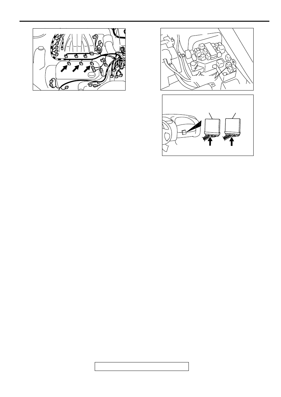
CONNECTORS : B-02, B-06, B-25
B-02 B-06 B-25
AK000226
AK000226AB
CONNECTOR : A-21X
MFI RELAY
AK000225
CONNECTOR : C-58<M/T>, C-55<A/T>
C-55
C-58
PCM<A/T>
ECM<M/T>
AI
MULTIPORT FUEL INJECTION (MFI) DIAGNOSIS
TSB Revision
MULTIPORT FUEL INJECTION (MFI) <3.0L ENGINE>
13B-229
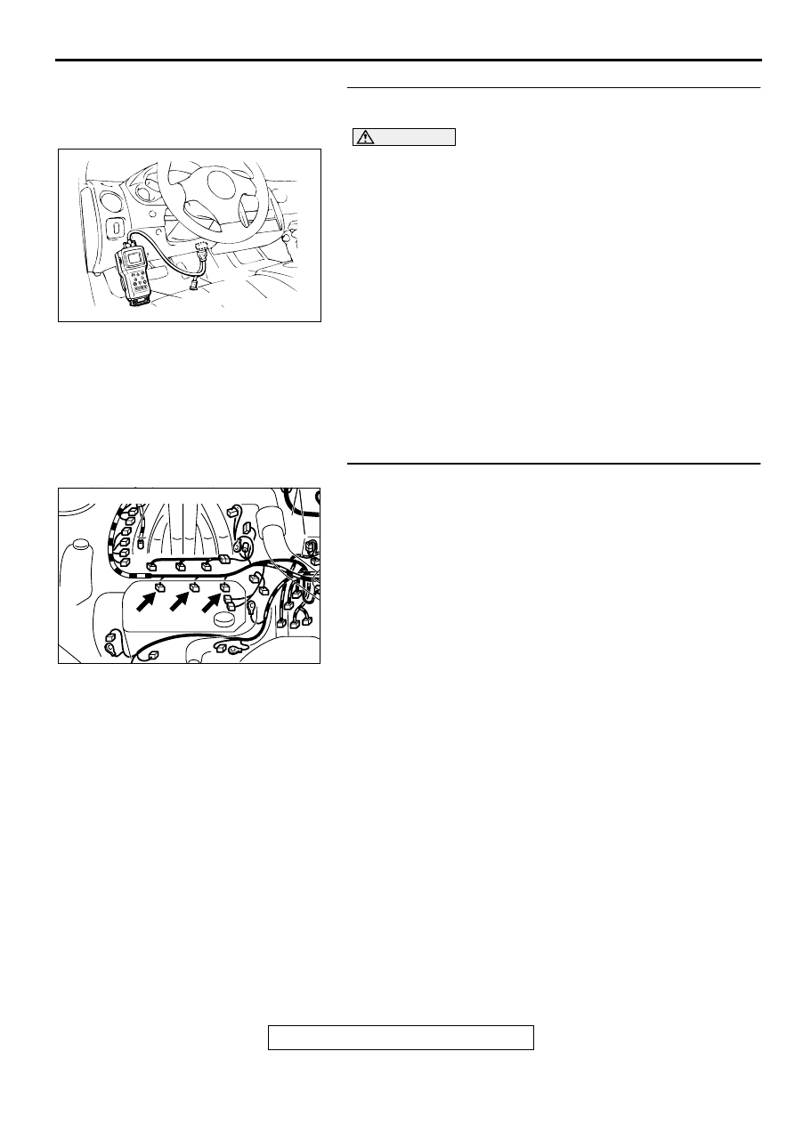
STEP 1. Using scan tool MB991502, check actuator test
item 02, 04, 06: Injectors.
CAUTION
To prevent damage to scan tool MB991502, always turn the
ignition switch to the "LOCK" (OFF) position before
connecting or disconnecting scan tool MB991502.
(1) Connect scan tool MB991502 to the data link connector.
(2) Start the engine and run at idle.
(3) Set scan tool MB991502 to the actuator testing mode for
item 02, 04, 06 Injectors.
(4) Warm up the engine to normal operating temperature: 80
°
C to 96
°
C (176
°
F to 205
°
F).
•
Does the idle state worsen when the injector is cut off.
(Does idling become unstable or does the engine stall)
(5) Turn the ignition switch to the "LOCK" (OFF) position.
Q: Is the actuator operating properly?
YES : It can be assumed that this malfunction is intermittent.
Refer to GROUP 00, How to Use Troubleshooting/
Inspection Service Points (
NO : Go to Step 2.
STEP 2. Check the connector at injector for damage.
a. Check the connector B-02 when checking No.2 cylinder.
b. Check the connector B-06 when checking No.4 cylinder.
c. Check the connector B-25 when checking No.6 cylinder.
Q: Is the connector in good condition?
YES : Go to Step 3.
NO : Repair or replace it. Refer to GROUP 00E, Harness
Connector Inspection (
). Then go to Step 10.
AKX01177
16 PIN
MB991502
AB
AK000213AB
CONNECTORS : B-02, B-06, B-25
B-02 B-06 B-25
MULTIPORT FUEL INJECTION (MFI) DIAGNOSIS
TSB Revision
MULTIPORT FUEL INJECTION (MFI) <3.0L ENGINE>
13B-230
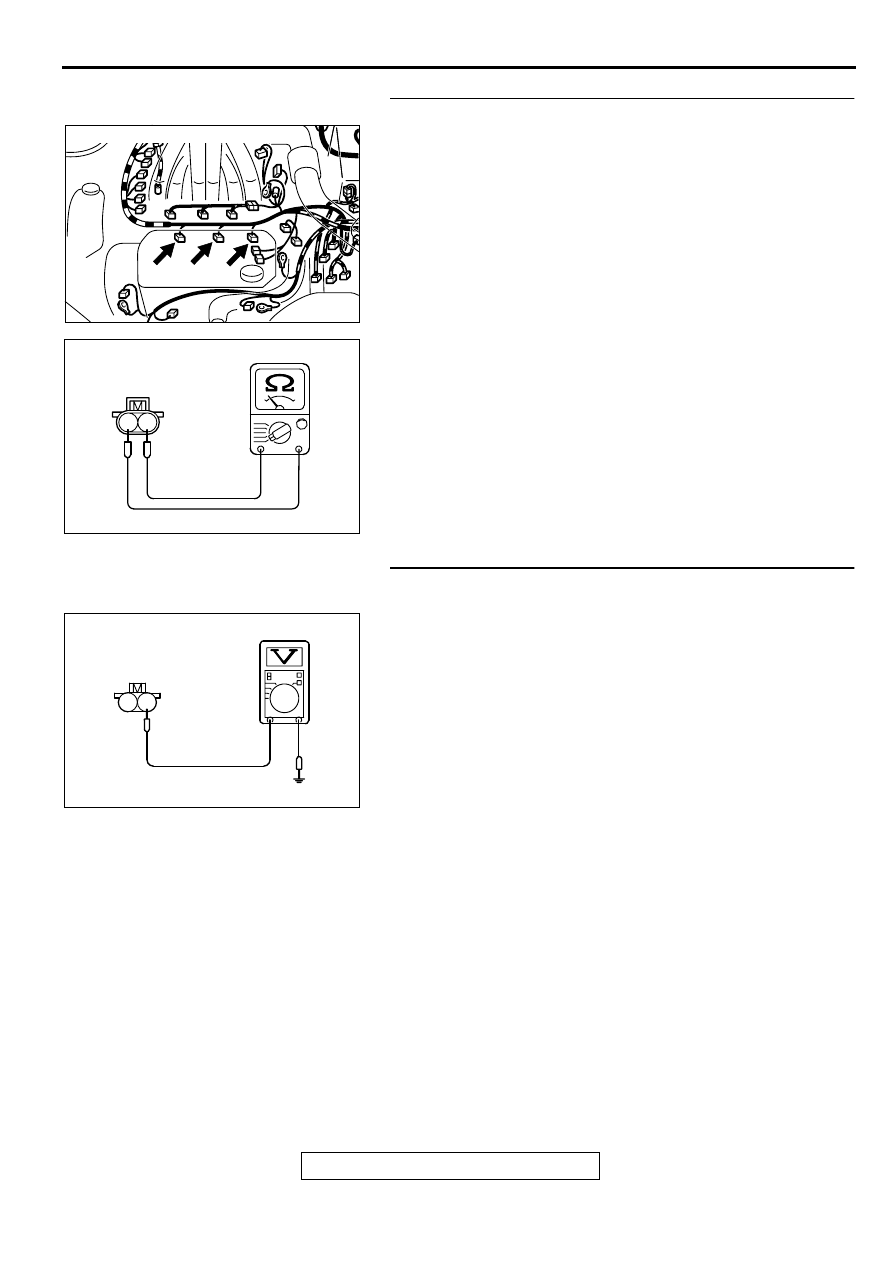
STEP 3. Check the injector.
(1) Disconnect the injector connector B-02 <No.2 cylinder> or
B-06 <No.4 cylinder> or B-25 <No.6 cylinder>.
(2) Measure the resistance between injector side connector
terminal 1 and 2.
Standard value: 13
−
16 ohm [at 20
°
C (68
°
F)]
Q: Is the resistance standard value?
YES : Go to Step 4.
NO : Replace the injector. Then go to Step 10.
STEP 4. Check the power supply voltage at injector
connector.
(1) Disconnect connector B-02 <No.2 cylinder> or B-06 <No.4
cylinder> or B-25 <No.6 cylinder> and measure at the
harness side.
(2) Turn the ignition switch to the "ON" position.
(3) Measure the voltage between terminal 1 and ground.
•
Voltage should be battery positive voltage.
(4) Turn the ignition switch to the "LOCK" (OFF) position.
Q: Is the voltage normal?
YES : Go to Step 6.
NO : Go to Step 5.
AK000213AB
CONNECTORS : B-02, B-06, B-25
B-02 B-06 B-25
AK000559
2
1
INJECTOR SIDE
CONNECTOR
AB
AK000560
2 1
B-02,B-06,B-25
HARNESS SIDE
CONNECTOR
AE
Нет комментариевНе стесняйтесь поделиться с нами вашим ценным мнением.
Текст