Mitsubishi Eclipse / Eclipse Spyder (2000-2002). Service and repair manual — part 136
MULTIPORT FUEL INJECTION (MFI) DIAGNOSIS
TSB Revision
MULTIPORT FUEL INJECTION (MFI) <2.4L ENGINE>
13A-243
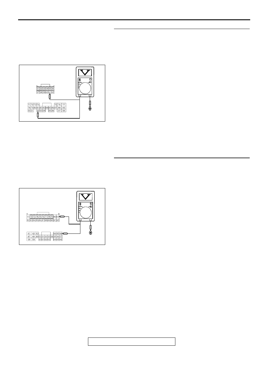
STEP 10. Check the output circuit voltage at ECM
connector C-56 <M/T> or PCM connector C-57 <A/T>.
(1) Do not disconnect the ECM connector C-56 <M/T> or PCM
connector C-57 <A/T>.
(2) Turn the ignition switch to the "ON" position.
(3) Remove the fuel cap.
(4) Measure the voltage between terminal 61 <M/T> or terminal
92 <A/T> and ground by backprobing.
•
Voltage should be between 2.0 and 3.0 volts.
(5) Turn the ignition switch to the "LOCK" (OFF) position.
Q: Is the multi-meter reading within the specified value?
YES : Go to Step 18.
NO : Check connectors D-16, C-90, C-28, C-56 <M/T> or
C-57 <A/T> and repair or replace as required. Refer
to GROUP 00E, Harness Connector Inspection
. If connectors D-16, C-90, C-28, C-56 <M/T>
or C-57 <A/T> are in good condition, check the
harness between intermediate connector D-16 and
ECM connector C-56 <M/T> or PCM connector C-57
<A/T> for open circuit or damage. Then repair if
necessary. Then go to Step 26.
STEP 11. Check the 5-volt supply circuit voltage at ECM
connector C-60 <M/T> or PCM connector C-54 <A/T>.
(1) Do not disconnect ECM connector C-60 <M/T> or PCM
connector C-54 <A/T>.
(2) Turn the ignition switch to the "ON" position.
(3) Measure the voltage between terminal 81 <M/T> or terminal
46 <A/T> and ground by backprobing.
•
Voltage should be between 4.8 and 5.2 volts.
(4) Turn the ignition switch to the "LOCK" (OFF) position.
Q: Is the multi-meter reading within the specified value?
YES : Check connectors D-16, C-90, C-28, C-60 <M/T> or
C-54 <A/T> and repair or replace as required. Refer
to GROUP 00E, Harness Connector Inspection
. If connectors D-16, C-90, C-28, C-60 <M/T>
or C-54 <A/T> are in good condition, check the
harness between intermediate connector D-16 and
ECM connector C-60 <M/T> or PCM connector C-54
<A/T> for open circuit or damage. Then repair if
necessary. Then go to Step 26.
NO : Go to Step 12.
AC002551AC
<M/T> C-56
<A/T> C-57
HARNESS SIDE
CONNECTOR
AC002552
HARNESS SIDE
CONNECTOR
<M/T> C-60
<A/T> C-54
AC
MULTIPORT FUEL INJECTION (MFI) DIAGNOSIS
TSB Revision
MULTIPORT FUEL INJECTION (MFI) <2.4L ENGINE>
13A-244
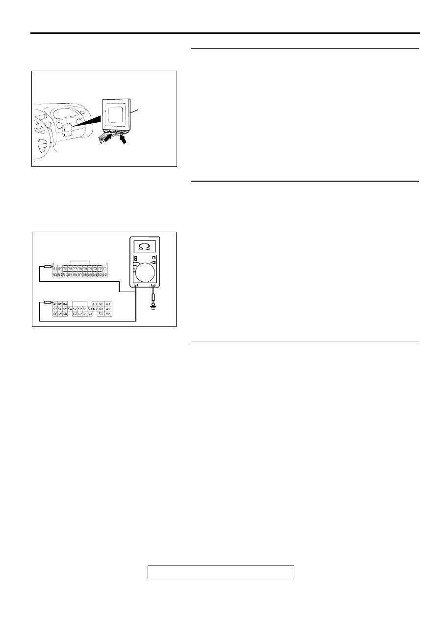
STEP 12. Check ECM connector C-60 <M/T> or PCM
connector C-54 <A/T> for damage.
(1) Disconnect ECM connector C-60 <M/T> or PCM connector
C-54 <A/T>.
Q: Is there any failure at ECM connector C-60 <M/T> or
PCM connector C-54 <A/T>?
YES : Repair or replace it. Refer to GROUP 00E, Harness
Connector Inspection
. Then go to Step 26.
NO : Go to Step 13.
STEP 13. Check the sensor power supply line for short
circuit to ground at ECM connector C-60 <M/T> or PCM
connector C-54 <A/T>.
(1) Disconnect ECM connector C-60 <M/T> or PCM connector
C-54 <A/T> and measure at the harness side.
(2) Check for the continuity between terminal 81 <M/T> or
terminal 46 <A/T> and ground.
•
There should be 2 ohms or more.
Q: Does the multi-meter reading exceed the specified
value?
YES : Replace ECM or PCM. Then go to Step 26.
NO : Go to Step 14.
STEP 14. Check the sensor power supply lines.
(1) Check all the sensor power supply lines for damage, which
flow through the harness ECM connector (terminal 81) <M/
T> or PCM connector (terminal 46) <A/T>.
Q: Is there any failure in the sensor power supply lines?
When a failure is found : Repair if necessary. (Refer to
GROUP 90, Circuit Diagrams
−
MFI System <M/T>
AC001689
CONNECTOR: C-60 <M/T>, C-54 <A/T>
ECM <M/T>
OR
PCM <A/T>
AL
C-54
<A/T>
C-60
<M/T>
AC002553
HARNESS SIDE
CONNECTOR
<M/T> C-60
<A/T> C-54
AC
MULTIPORT FUEL INJECTION (MFI) DIAGNOSIS
TSB Revision
MULTIPORT FUEL INJECTION (MFI) <2.4L ENGINE>
13A-245
STEP 15. Check the ground circuit voltage at ECM
connector C-60 <M/T> or PCM connector C-54 <A/T>.
(1) Do not disconnect ECM connector C-60 <M/T> or PCM
connector C-54 <A/T>.
(2) Turn the ignition switch to the "ON" position.
(3) Measure the voltage between terminal 92 <M/T> or 57 <A/
T> and ground by backprobing.
•
Voltage should be 0.5 volts or less.
(4) Turn the ignition switch to the "LOCK" (OFF) position.
Q: Is the multi-meter reading below the specified value?
YES : Check connectors D-16, C-90, C-28, C-60 <M/T> or
C-54 <A/T> and repair or replace as required. Refer
to GROUP 00E, Harness Connector Inspection
. If connectors D-16, C-90, C-28, C-60 <M/T>
or C-54 <A/T> are in good condition, check the
harness between intermediate connector D-16 and
ECM connector C-60 <M/T> or PCM connector C-54
<A/T> for open circuit or damage. Then repair if
necessary. Then go to Step 26.
NO : Go to Step 16.
STEP 16. Check ECM connector C-60 <M/T> or PCM
connector C-54 <A/T> for damage.
(1) Disconnect ECM connector C-60 <M/T> or PCM connector
C-54 <A/T>.
Q: Is there any failure at ECM connector C-60 <M/T> or
PCM connector C-54 <A/T>?
YES : Repair or replace it. Refer to GROUP 00E, Harness
Connector Inspection
. Then go to Step 26.
NO : Go to Step 26.
AC002554 AC
<M/T> C-60
<A/T> C-54
HARNESS SIDE
CONNECTOR
AC001689
CONNECTOR: C-60 <M/T>, C-54 <A/T>
ECM <M/T>
OR
PCM <A/T>
AL
C-54
<A/T>
C-60
<M/T>
MULTIPORT FUEL INJECTION (MFI) DIAGNOSIS
TSB Revision
MULTIPORT FUEL INJECTION (MFI) <2.4L ENGINE>
13A-246
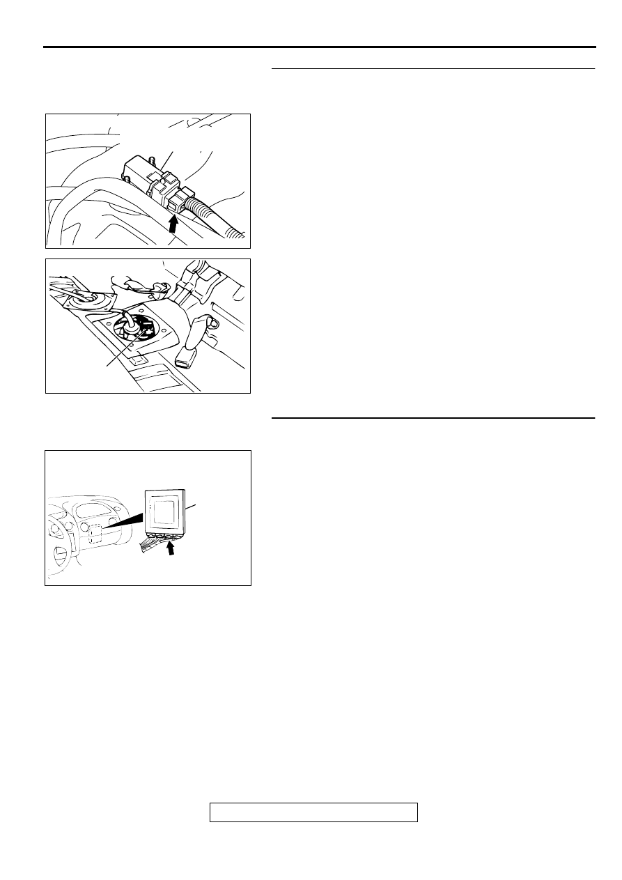
STEP 17. Check the harness between fuel tank differential
pressure sensor connector D-18 and intermediate
connector D-16 for open circuit or damage.
(1) Disconnect fuel tank differential pressure sensor connector
D-18 and intermediate connector D-16.
Q: Is there any failure between fuel tank differential
pressure sensor connector D-18 and intermediate
connector D-16?
YES : Repair it. Then go to Step 26.
NO : Check connectors D-18, D-16 and repair or replace
as required. Refer to GROUP 00e, Harness
Connector Inspection
. Then go to Step 26.
STEP 18. Check ECM connector C-56 <M/T> or PCM
connector C-57 <A/T> for damage.
(1) Disconnect ECM connector C-56 <M/T> or PCM connector
C-57 <A/T>.
Q: Is there any failure at ECM connector C-56 <M/T> or
PCM connector C-57 <A/T>?
YES : Go to Step 26.
NO : Repair or replace it. Refer to GROUP 00e, Harness
Connector Inspection
. Then go to Step 26.
AC002041AB
CONNECTOR: D-18
FUEL TANK DIFFERENTIAL
PRESSURE SENSOR
AC002549 AB
CONNECTOR: D-16
INTERMEDIATE
CONNECTOR
AC001689
CONNECTOR: C-56 <M/T>, C-57 <A/T>
ECM <M/T>
OR
PCM <A/T>
C-56 <M/T>,
C-57 <A/T>
AM
Нет комментариевНе стесняйтесь поделиться с нами вашим ценным мнением.
Текст