Mitsubishi Eclipse / Eclipse Spyder (2000-2002). Service and repair manual — part 135
MULTIPORT FUEL INJECTION (MFI) DIAGNOSIS
TSB Revision
MULTIPORT FUEL INJECTION (MFI) <2.4L ENGINE>
13A-239
•
The ECM <M/T> or PCM <A/T> must see this
activity during 8 consecutive idling periods from
engine starting.
NOTE: Rapid voltage occurs due to fuel sloshing
during refuelling. However, when the PCM sees
the activity mentioned above 8 consecutive
times, it judges that an electrical noise is present.
NOTE: The PCM determines that the engine is
not idling if all of the following conditions are met.
.
•
Engine speed is higher than 2,500 r/min.
•
Vehicle speed is 15 km/h (9.3 mph) or more.
•
Volumetric efficiency is 55 percent or more.
TROUBLESHOOTING HINTS
The most likely causes for this code to be set are:
•
Fuel tank differential pressure sensor failed.
•
Open or shorted fuel tank differential pressure
sensor circuit, or loose connector.
•
ECM failed <M/T>.
•
PCM failed <A/T>.
•
Blockage of evaporative emission system
(causing high pressure).
OVERVIEW OF TROUBLESHOOTING
•
The DTC P0450 can be set if either of the
following conditions occur:
1. Faulty fuel differential pressure sensor,
related circuit, or ECM <M/T> or PCM <A/T>.
2. Faulty fuel filler neck evaporative emission
ventilation solenoid or blocked vapor line.
•
To check a system blockage, do a performance
test which uses a mechanical vacuum gauge and
the scan tool MB991502 set on the fuel tank
differential pressure sensor (TANK PRS
SNSR73.)
The mechanical gauge reading is used to verify
the scan tool MB991502 reading.
A comparison of the mechanical gauge to the
scan tool MB991502 determines the problem in
the system.
DIAGNOSIS
Required Special Tools:
•
MB991502: Scan Tool (MUT-II)
•
MB991658: Test Harness Set
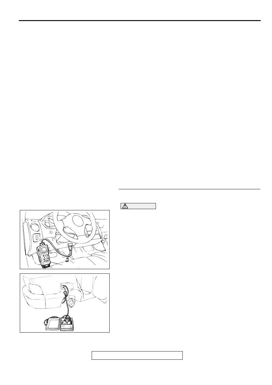
STEP 1. Using scan tool MB991502, check data list item 73:
Fuel Tank Differential Pressure Sensor.
CAUTION
To prevent damage to scan tool MB991502, always turn the
ignition switch to "LOCK" (OFF) position before
connecting or disconnecting scan tool MB991502.
(1) Connect scan tool MB991502 to the data link connector.
(2) Turn the ignition switch to the "ON" position.
(3) Remove the fuel cap.
(4) Set scan tool MB991502 to the data reading mode for item
73, Fuel Tank Differential Pressure Sensor.
•
The fuel tank pressures should be
−
1.5 to 1.5kPa.
(5) Connect an evaporative emission system pressure pump to
the fuel filler neck, and apply pressure.
•
The scan tool reading should increase.
Q: Is the scan tool reading within the specified value?
YES : Go to Step 20.
NO : Go to Step 2.
AC001252
MB991502
16 PIN
AB
AC000186
MULTIPORT FUEL INJECTION (MFI) DIAGNOSIS
TSB Revision
MULTIPORT FUEL INJECTION (MFI) <2.4L ENGINE>
13A-240
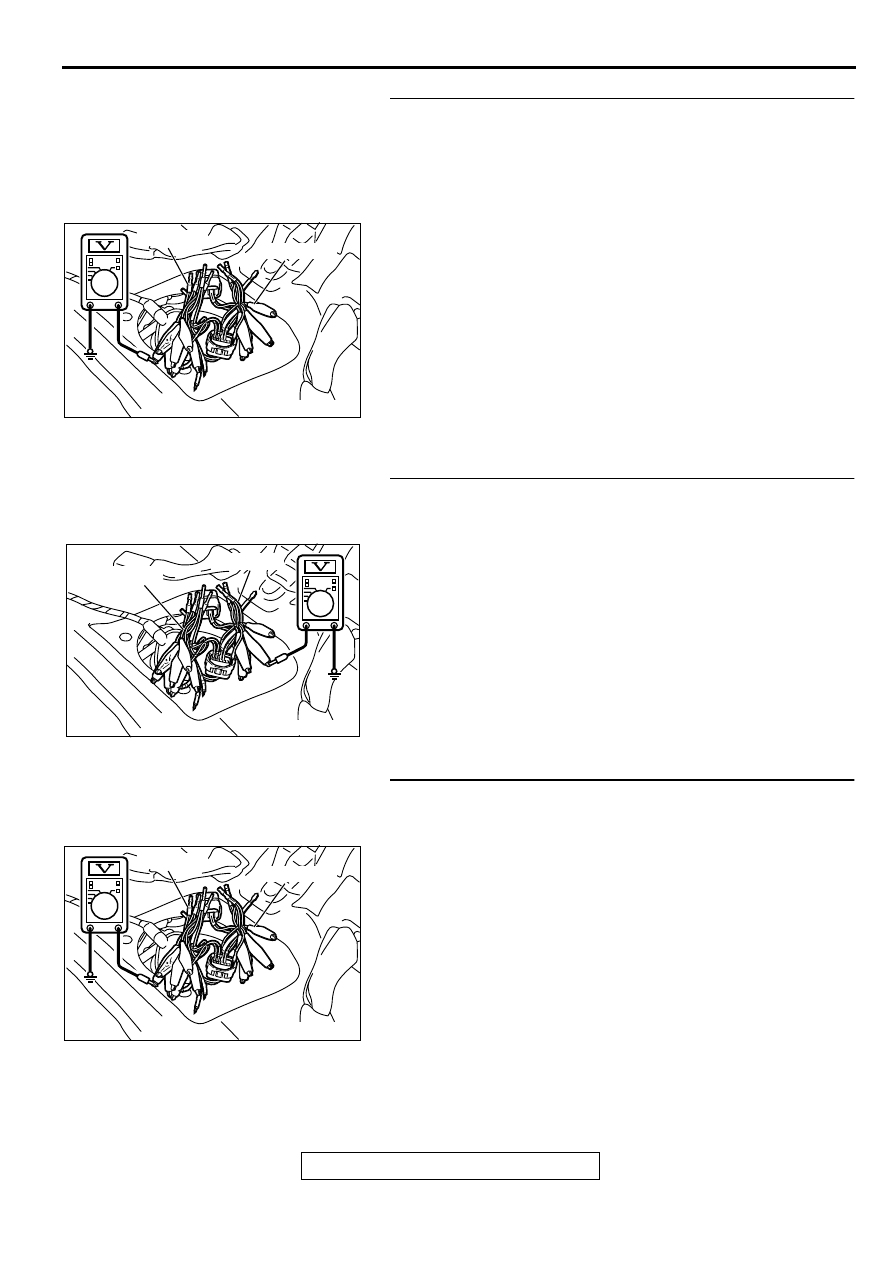
STEP 2. Check the output circuit voltage at intermediate
connector D-16.
(1) Remove the rear seat cushion. (Refer to GROUP 52A, Rear
(2) Remove the protector.
(3) Do not disconnect intermediate connector D-16.
(4) Use special tools (MB991658 and MB991709) to connect
terminals 5, 6 and 8 between connectors of the
intermediate connector, respectively.
(5) Turn the ignition switch to the "ON" position.
(6) Remove the fuel cap.
(7) Measure the voltage between terminal 5 and ground by
backprobing.
•
Voltage should be between 2.0 and 3.0 volts.
(8) Turn the ignition switch to the "LOCK" (OFF) position.
Q: Is the multi-meter reading within the specified value?
YES : Go to Step 10.
NO : Go to Step 3.
STEP 3. Check the 5-volt supply circuit voltage at
intermediate connector D-16.
(1) Do not disconnect intermediate connector D-16.
(2) Use special tools (MB991658 and MB991709) to connect
terminals 5, 6 and 8 between connectors of the
intermediate connector, respectively.
(3) Turn the ignition switch to the "ON" position.
(4) Measure the voltage between terminal 8 and ground by
backprobing.
•
Voltage should be between 4.8 and 5.2 volts.
(5) Turn the ignition switch to the "LOCK" (OFF) position.
Q: Is the multi-meter reading within the specified value?
YES : Go to Step 4.
NO : Go to Step 11.
STEP 4. Check the ground circuit voltage at intermediate
connector D-16.
(1) Do not disconnect intermediate connector D-16.
(2) Use special tools (MB991658 and MB991709) to connect
terminals 5, 6 and 8 between connectors of the
intermediate connector, respectively.
(3) Turn the ignition switch to the "ON" position.
(4) Measure the voltage between terminal 6 and ground by
backprobing.
•
Voltage should be between 0.5 volts or less.
(5) Turn the ignition switch to the "LOCK" (OFF) position.
Q: Is the multi-meter reading within the specified value?
YES : Go to Step 5.
NO : Go to Step 15.
AC002079 AB
MB991709
MB991658
AC002080
MB991709
MB991658
AB
AC002079 AB
MB991709
MB991658
MULTIPORT FUEL INJECTION (MFI) DIAGNOSIS
TSB Revision
MULTIPORT FUEL INJECTION (MFI) <2.4L ENGINE>
13A-241
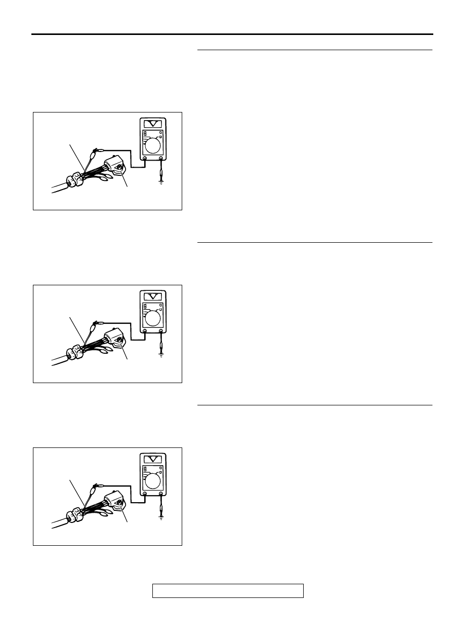
STEP 5. Check the output circuit voltage at fuel tank
differential pressure connector D-18.
(1) Remove the center pipe.
(2) Remove the fuel band assembly, tilt the fuel tank.
(3) Disconnect fuel tank differential pressure sensor connector
D-18.
(4) Use special tool (MB991658) to connect terminals 1, 2 and
3 of the disconnected sensor connector and those of the
harness side connector, respectively.
(5) Turn the ignition switch to the "ON" position.
(6) Remove the fuel cap.
(7) Measure the voltage between terminal 1 and ground by
backprobing.
•
Voltage should be between 2.0 and 3.0 volts.
(8) Turn the ignition switch to the "LOCK" (OFF) position.
Q: Is the multi-meter reading within the specified value?
YES : Go to Step 17.
NO : Go to Step 6.
STEP 6. Check the 5-volt supply circuit voltage at fuel tank
differential pressure sensor connector D-18.
(1) Do not disconnect fuel tank differential pressure sensor
connector D-18.
(2) Use special tool (MB991658) to connect terminals 1, 2 and
3 of the disconnected sensor connector and those of the
harness side connector, respectively.
(3) Turn the ignition switch to the "ON" position.
(4) Measure the voltage between terminal 3 and ground by
backprobing.
•
Voltage should be between 4.8 and 5.2 volts.
(5) Turn the ignition switch to the "LOCK" (OFF) position.
Q: Is the multi-meter reading within the specified value?
YES : Go to Step 7.
NO : Go to Step 17.
STEP 7. Check the ground circuit voltage at fuel tank
differential pressure sensor connector D-18.
(1) Disconnect fuel tank differential pressure sensor connector
D-18.
(2) Use special tool (MB991658) to connect terminals 1, 2 and
3 of the disconnected sensor connector and those of the
harness side connector, respectively.
(3) Turn the ignition switch to the "ON" position.
(4) Measure the voltage between terminal 2 and ground by
backprobing.
•
Voltage should be between 0.5 volts or less.
(5) Turn the ignition switch to the "LOCK" (OFF) position.
Q: Is the multi-meter reading within the specified value?
YES : Go to Step 8.
NO : Go to Step 17.
AC002081AB
MB991658
FUEL TANK DIFFERENTIAL
PRESSURE SENSOR
AC002081AB
MB991658
FUEL TANK DIFFERENTIAL
PRESSURE SENSOR
AC002081AB
MB991658
FUEL TANK DIFFERENTIAL
PRESSURE SENSOR
MULTIPORT FUEL INJECTION (MFI) DIAGNOSIS
TSB Revision
MULTIPORT FUEL INJECTION (MFI) <2.4L ENGINE>
13A-242
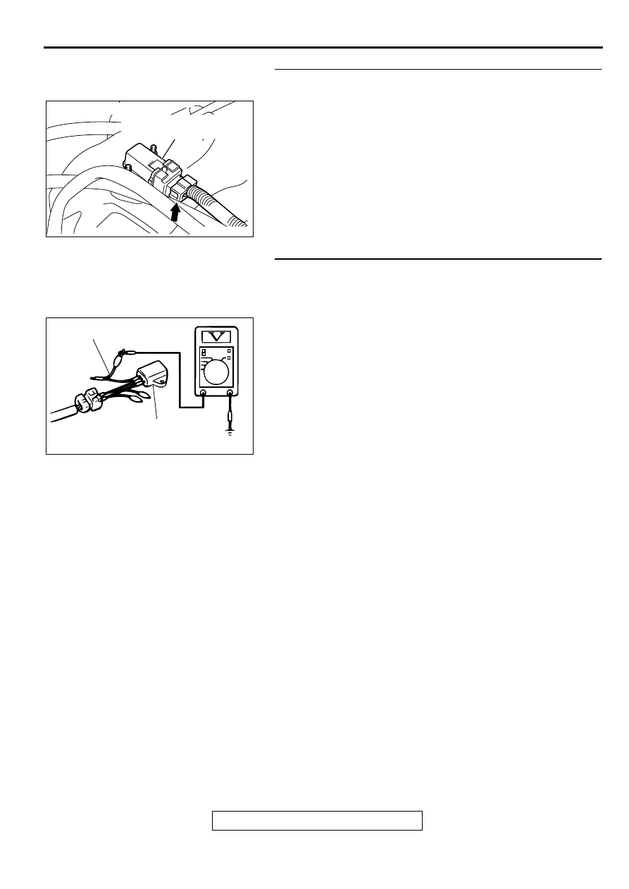
STEP 8. Check fuel tank differential pressure sensor
connector D-18 for damage.
(1) Disconnect fuel tank differential pressure sensor connector
D-18.
Q: Is there any failure at fuel tank differential pressure
sensor connector D-18?
YES : Go to Step 9.
NO : Repair or replace it. Refer to GROUP 00E, Harness
Connector Inspection
. Then go to Step 26.
STEP 9. Check the output voltage at fuel tank differential
pressure sensor connector D-18.
(1) Disconnect fuel tank differential pressure sensor connector
D-18.
(2) Use special tool (MB991658) to connect terminals 2 and 3
of the disconnected sensor connector and those of the
harness side connector, respectively.
(3) Turn the ignition switch to the "ON" position.
(4) Remove the fuel cap.
(5) Measure the voltage between terminal 1 and ground by
backprobing.
•
Voltage should be between 2.0 and 3.0 volts.
(6) Turn the ignition switch to the "LOCK" (OFF) position.
Q: Is the multi-meter reading within the specified value?
YES : Check connectors D-16, C-90, C-28, C-56 <M/T> or
C-57 <A/T> and repair or replace as required. Refer
to GROUP 00E, Harness Connector Inspection
. If connectors D-16, C-90, C-28, C-56 <M/T>
or C-57 <A/T> are in good condition, check the
harness between fuel tank differential pressure
sensor connector D-18 and ECM connector C-56 <M/
T> or PCM connector C-57 <A/T> for short circuit to
ground, then repair if necessary. Then go to Step 26.
NO : Replace the fuel tank differential pressure sensor.
Then go to Step 26.
AC002041AB
CONNECTOR: D-18
FUEL TANK DIFFERENTIAL
PRESSURE SENSOR
ACX01760AB
MB991658
FUEL TANK DIFFERENTIAL
PRESSURE SENSOR
Нет комментариевНе стесняйтесь поделиться с нами вашим ценным мнением.
Текст