Mitsubishi Eclipse / Eclipse Spyder (2000-2002). Service and repair manual — part 100

MULTIPORT FUEL INJECTION (MFI) DIAGNOSIS
TSB Revision
MULTIPORT FUEL INJECTION (MFI) <2.4L ENGINE>
13A-99
TECHNICAL DESCRIPTION
•
The TPS outputs voltage which corresponds to
the throttle valve opening angle.
•
The ECM <M/T> or PCM <A/T> checks whether
the voltage is within a specified range.
DTC SET CONDITIONS
Check Conditions
•
Two seconds or more have passed since the
staring sequence was completed.
•
Engine speed is higher than 2,000 r/min.
•
Volumetric efficiency is higher than 60 percent.
Judgement Criteria
•
TPS output voltage has continued to be 0.8 volt
or lower for 2 seconds.
TROUBLESHOOTING HINTS (The most likely
causes for this code to be set are:)
•
TPS failed or maladjusted.
•
Open or shorted TPS circuit, or loose connector.
•
ECM failed. <M/T>
•
PCM failed. <A/T>
DIAGNOSIS
Required Special Tools
MB991502: Scan Tool (MUT-II)
STEP 1. Using scan tool MB991502, check data list item 14:
Throttle Position Sensor.
CAUTION
To prevent damage to scan tool MB991502, always turn the
ignition switch to the "LOCK" (OFF) position before
connecting or disconnecting scan tool MB991502.
(1) Connect scan tool MB991502 to the data link connector.
(2) Turn the ignition switch to the "ON" position.
(3) Set scan tool MB991502 to the data reading mode for item
14, Throttle Position Sensor.
•
With the throttle valve in the idle position, voltage should
be between 0.535 and 0.735 volts.
•
With the throttle valve in the full-open position, voltage
should be between 4.5 and 5.5 volts.
(4) Turn the ignition switch to the "LOCK" (OFF) position.
Q: Is the sensor operating properly?
YES : It can be assumed that this malfunction is intermittent.
Refer to GROUP 00, How to Use Troubleshooting/
Inspection Service Points (
NO : Go to Step 2.
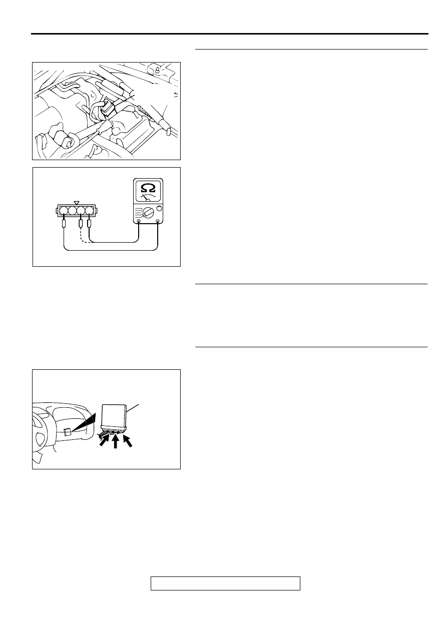
STEP 2. Check connector B-07 at throttle position sensor
for damage.
Q: Is the connector in good condition?
YES : Go to Step 3.
NO : Repair or replace it. Refer to GROUP 00E, Harness
Connector Inspection (
). Then go to Step 9.
AKX01177
16 PIN
MB991502
AB
ACX02472
CONNECTOR : B-07
THROTTLE
POSITION
SENSOR
AE
MULTIPORT FUEL INJECTION (MFI) DIAGNOSIS
TSB Revision
MULTIPORT FUEL INJECTION (MFI) <2.4L ENGINE>
13A-100
STEP3. Check the throttle position sensor.
(1) Disconnect the connector B-07.
(2) Measure the resistance between throttle position sensor
side connector terminal 1 and 4.
Standard value: 3.5
−
6.5 k
Ω
(3) Measure resistance between the throttle position sensor
side connector terminal 1 and 3.
(4) Move the throttle valve from the idle position to the full-open
position.
•
Resistance should change smoothly in proportion to the
opening angle of the throttle valve.
Q: Is the resistance normal?
YES : Go to Step 4.
NO : Replace the throttle position sensor.(Refer to
, Throttle Body.) Then go to Step 9.
STEP 4. Check the maladjusted throttle position sensor.
Refer to, Throttle Position Sensor Adjustment (
Q: Is the output voltage normal?
YES : Go to Step 5.
NO : Adjust it. Then go to Step 9.
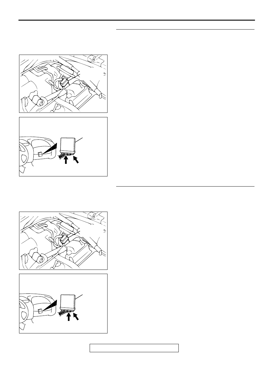
STEP 5. Check connector C-60 at ECM <M/T> or connector
C-54, C-57 at PCM <A/T> for damage.
Q: Is the connector in good condition?
YES : Go to Step 6.
NO : Repair or replace it. Refer to GROUP 00E, Harness
Connector Inspection (
). Then go to Step 9.
ACX02472
CONNECTOR : B-07
THROTTLE
POSITION
SENSOR
AE
AK000320
1 2 3 4
THROTTLE POSITION
SENSOR SIDE
CONNECTOR
AB
AK000280
C-54
C-60
ECM<M/T>
OR
PCM<A/T>
CONNECTORS:C-60<M/T>,C-54,C-57<A/T>
BD
C-57
MULTIPORT FUEL INJECTION (MFI) DIAGNOSIS
TSB Revision
MULTIPORT FUEL INJECTION (MFI) <2.4L ENGINE>
13A-101
STEP 6. Check for harness damage between throttle
position sensor connector B-07 terminal 4 and ECM
connector C-60 terminal 81 <M/T> or PCM connector C-54
terminal 46 <A/T>.
Q: Is the harness wire in good condition?
YES : Go to Step 7.
NO : Repair it. Then go to Step 9.
STEP 7. Check for harness damage between throttle
position sensor connector B-07 terminal 3 and ECM
connector C-60 terminal 84 <M/T> or PCM connector C-57
terminal 78 <A/T>.
Q: Is the harness wire in good condition?
YES : Go to Step 8.
NO : Repair it. Then go to Step 9.
ACX02472
CONNECTOR : B-07
THROTTLE
POSITION
SENSOR
AE
AK000280
C-54
C-60
ECM<M/T>
OR
PCM<A/T>
CONNECTORS:C-60<M/T>,C-54<A/T>
BB
ACX02472
CONNECTOR : B-07
THROTTLE
POSITION
SENSOR
AE
AK000280
C-60
ECM<M/T>
OR
PCM<A/T>
CONNECTORS:C-60<M/T>,C-57<A/T>
BE
C-57

MULTIPORT FUEL INJECTION (MFI) DIAGNOSIS
TSB Revision
MULTIPORT FUEL INJECTION (MFI) <2.4L ENGINE>
13A-102
STEP 8. Using scan tool MB991502, check data list item 14:
Throttle Position Sensor.
CAUTION
To prevent damage to scan tool MB991502, always turn the
ignition switch to the "LOCK" (OFF) position before
connecting or disconnecting scan tool MB991502.
(1) Connect scan tool MB991502 to the data link connector.
(2) Turn the ignition switch to the "ON" position.
(3) Set scan tool MB991502 to the data reading mode for item
14, Throttle Position Sensor.
•
With the throttle valve in the idle position, voltage should
be between 0.535 and 0.735 volts.
•
With the throttle valve in the full-open position, voltage
should be between 4.5 and 5.5 volts.
(4) Turn the ignition switch to the "LOCK" (OFF) position.
Q: Is the sensor operating properly?
YES : It can be assumed that this malfunction is intermittent.
Refer to GROUP 00, How to Use Troubleshooting/
Inspection Service Points (
NO : Replace the ECM or PCM. Then go to Step 9.
STEP 9. Test the OBD-II drive cycle.
(1) Carry out a test drive with the drive cycle pattern. Refer to,
Procedure 6
−
Other Monitor (
).
(2) Check the diagnostic trouble code (DTC).
Q: Is the DTC P0122 is output?
YES : Retry the troubleshooting.
NO : The inspection is complete.
AKX01177
16 PIN
MB991502
AB
Нет комментариевНе стесняйтесь поделиться с нами вашим ценным мнением.
Текст