Mitsubishi Eclipse / Eclipse Spyder (2000-2002). Service and repair manual — part 99
MULTIPORT FUEL INJECTION (MFI) DIAGNOSIS
TSB Revision
MULTIPORT FUEL INJECTION (MFI) <2.4L ENGINE>
13A-95
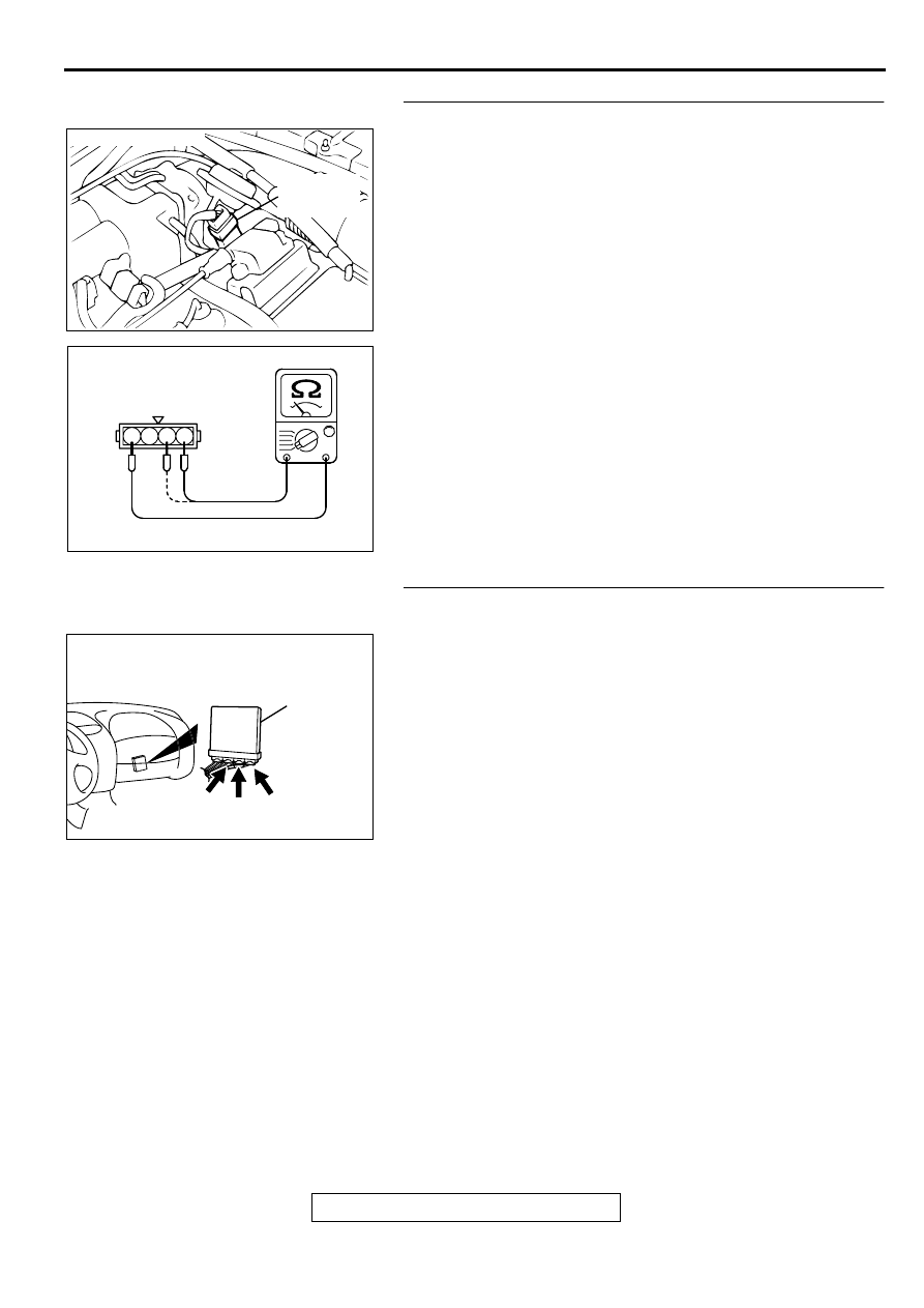
STEP 9. Check the throttle position sensor.
(1) Disconnect the connector B-07.
(2) Measure the resistance between throttle position sensor
side connector terminal 1 and 4.
Standard value: 3.5
−
6.5 k
Ω
(3) Measure resistance between the throttle position sensor
side connector terminal 1 and 3.
(4) Move the throttle valve from the idle position to the full-open
position.
•
Resistance should change smoothly in proportion to the
opening angle of the throttle valve.
Q: Is the resistance normal?
YES : Go to Step 10.
NO : Replace the throttle position sensor.(Refer to
, Throttle Body.) Then go to Step 14.
STEP 10. Check connector C-60 at ECM <M/T> or
connector C-54, C-57 at PCM <A/T> for damage.
Q: Is the connector in good condition?
YES : Go to Step 11.
NO : Repair or replace it. Refer to GROUP 00E, Harness
Connector Inspection (
). Then go to Step 14.
ACX02472
CONNECTOR : B-07
THROTTLE
POSITION
SENSOR
AE
AK000320
1 2 3 4
THROTTLE POSITION
SENSOR SIDE
CONNECTOR
AB
AK000280
C-54
C-60
ECM<M/T>
OR
PCM<A/T>
CONNECTORS:C-60<M/T>,C-54,C-57<A/T>
BD
C-57
MULTIPORT FUEL INJECTION (MFI) DIAGNOSIS
TSB Revision
MULTIPORT FUEL INJECTION (MFI) <2.4L ENGINE>
13A-96
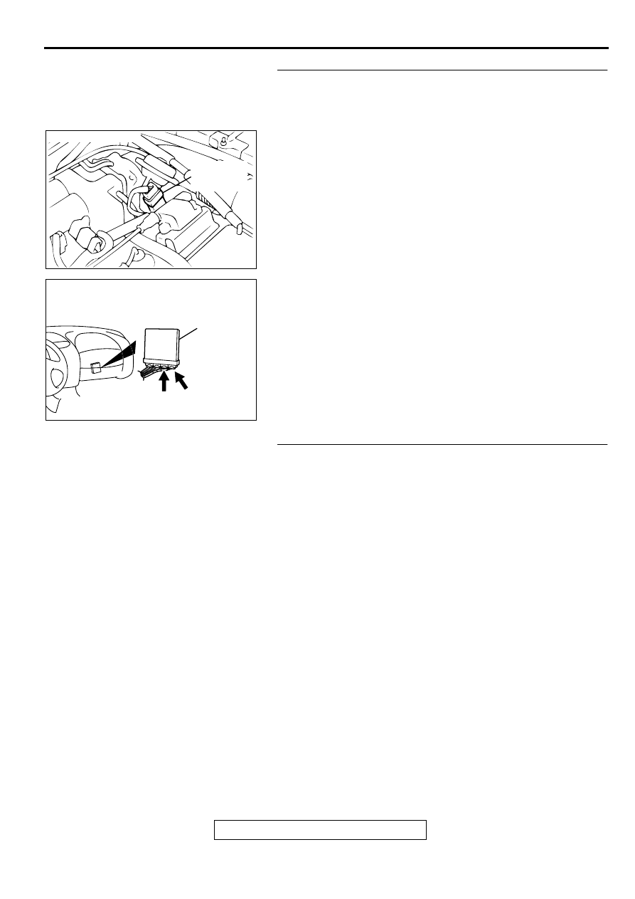
STEP 11. Check for open circuit and short circuit to ground
between throttle position sensor connector B-07 terminal 3
and ECM connector C-60 terminal 84 <M/T> or PCM
connector C-57 terminal 78 <A/T>.
Q: Is the harness wire in good condition?
YES : Go to Step 12.
NO : Repair it. Then go to Step 14.
STEP 12. Check for short circuit to ground between
throttle position sensor connector and auto-cruise control-
ECU.
Refer to GROUP 17, Auto Cruise Control System-Diagnostic
Trouble Code Chart (
Q: Is the harness wire in good condition?
YES : Go to Step 13.
NO : Repair it. Then go to Step 14.
ACX02472
CONNECTOR : B-07
THROTTLE
POSITION
SENSOR
AE
AK000280
C-60
ECM<M/T>
OR
PCM<A/T>
CONNECTORS:C-60<M/T>,C-57<A/T>
BE
C-57

MULTIPORT FUEL INJECTION (MFI) DIAGNOSIS
TSB Revision
MULTIPORT FUEL INJECTION (MFI) <2.4L ENGINE>
13A-97
STEP 13. Using scan tool MB991502, check data list item
14: Throttle Position Sensor.
CAUTION
To prevent damage to scan tool MB991502, always turn the
ignition switch to the "LOCK" (OFF) position before
connecting or disconnecting scan tool MB991502.
(1) Connect scan tool MB991502 to the data link connector.
(2) Turn the ignition switch to the "ON" position.
(3) Set scan tool MB991502 to the data reading mode for item
14, Throttle Position Sensor.
•
With the throttle valve in the idle position, voltage should
be between 0.535 and 0.735 volts.
•
With the throttle valve in the full-open position, voltage
should be between 4.5 and 5.5 volts.
(4) Turn the ignition switch to the "LOCK" (OFF) position.
Q: Is the sensor operating properly?
YES : It can be assumed that this malfunction is intermittent.
Refer to GROUP 00, How to Use Troubleshooting/
Inspection Service Points (
NO : Replace the ECM or PCM. Then go to Step 14.
STEP 14. Test the OBD-II drive cycle.
(1) Carry out a test drive with the drive cycle pattern. Refer to,
Procedure 6
−
Other Monitor (
).
(2) Check the diagnostic trouble code (DTC).
Q: Is the DTC P0121 is output?
YES : Retry the troubleshooting.
NO : The inspection is complete.
AKX01177
16 PIN
MB991502
AB
MULTIPORT FUEL INJECTION (MFI) DIAGNOSIS
TSB Revision
MULTIPORT FUEL INJECTION (MFI) <2.4L ENGINE>
13A-98
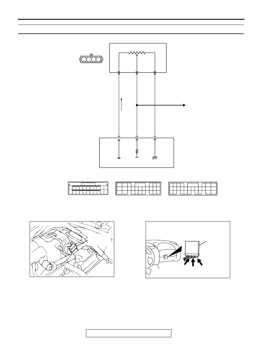
DTC P0122: Throttle Position Circuit Low Input
CIRCUIT OPERATION
•
A 5-volt power supply is applied on the TPS
power terminal (terminal 4) from the ECM
(terminal 81) <M/T> or PCM (terminal 46) <A/T>.
The ground terminal (terminal 1) is grounded with
ECM (terminal 92) <M/T> or PCM (terminal 57)
<A/T>.
•
When the throttle valve shaft is turned from the
idle position to the fully opened position, the
resistor between the TPS output terminal
(terminal 3) and ground terminal will increase
according to the rotation.
AK000656
2 3 4
1
98
78
71
88 89
76 77
72
79
91
73
80
74
75
81
92
8283
93
8485
94
8687
9596
90
97
GREEN-YELLO
W
YELLO
W
YELLO
W
BLA
CK
ENGINE CONTROL
MODULE(ECM)<M/T>
OR
POWERTRAIN CONTROL
MODULE(PCM)<A/T>
92<M/T>
57<A/T>*1
84<M/T>
78<A/T>*2
81<M/T>
46<A/T>*1
5V
C-60<M/T>
(MU803772)
C-54<A/T>
(MU803781)
C-57<A/T>
(MU803782)
AUTO-CRUISE
CONTROL SYSTEM
B-07
(MU802724)
THROTTLE POSITION
SENSOR
NOTE
*1:PCM connector C-54<A/T>
*2:PCM connector C-57<A/T>
4
3
1
82
78
81
80
89 90 91 92
79
87
71
74
73
72
76
75
77
85
88
83 84
86
42 43
48 49 50 51 52 53 54 55 56 57
46
45
44
58 59
60 61 62 63
64 65 66
47
41
ACX02472
CONNECTOR : B-07
THROTTLE
POSITION
SENSOR
AE
AK000280
C-54
C-60
ECM<M/T>
OR
PCM<A/T>
CONNECTORS:C-60<M/T>,C-54,C-57<A/T>
BD
C-57
Нет комментариевНе стесняйтесь поделиться с нами вашим ценным мнением.
Текст