Mitsubishi Eclipse / Eclipse Spyder (2000-2002). Service and repair manual — part 98
MULTIPORT FUEL INJECTION (MFI) DIAGNOSIS
TSB Revision
MULTIPORT FUEL INJECTION (MFI) <2.4L ENGINE>
13A-91
TECHNICAL DESCRIPTION
•
The TPS outputs voltage which corresponds to
the throttle valve opening angle.
•
The ECM <M/T> or PCM <A/T> checks whether
the voltage is within a specified range. In
addition, it checks that the voltage output does
not become too high while the engine is at idle.
DTC SET CONDITIONS
Check Conditions
•
Two seconds or more have passed since the
starting sequence was completed.
Judgement Criteria
•
The sensor output voltage remains 2 volts or
more for two seconds when engine speed is
1,000 r/min or less, and volumetric efficiency is
60% or less.
or
•
TPS output voltage has continued to be 0.2 volt
or lower for 2 seconds.
TROUBLESHOOTING HINTS (The most likely
causes for this code to be set are:)
•
TPS failed or maladjusted.
•
Open or shorted TPS circuit, or loose connector.
•
ECM failed. <M/T>
•
PCM failed. <A/T>
DIAGNOSIS
Required Special Tools
MB991502: Scan Tool (MUT-II)
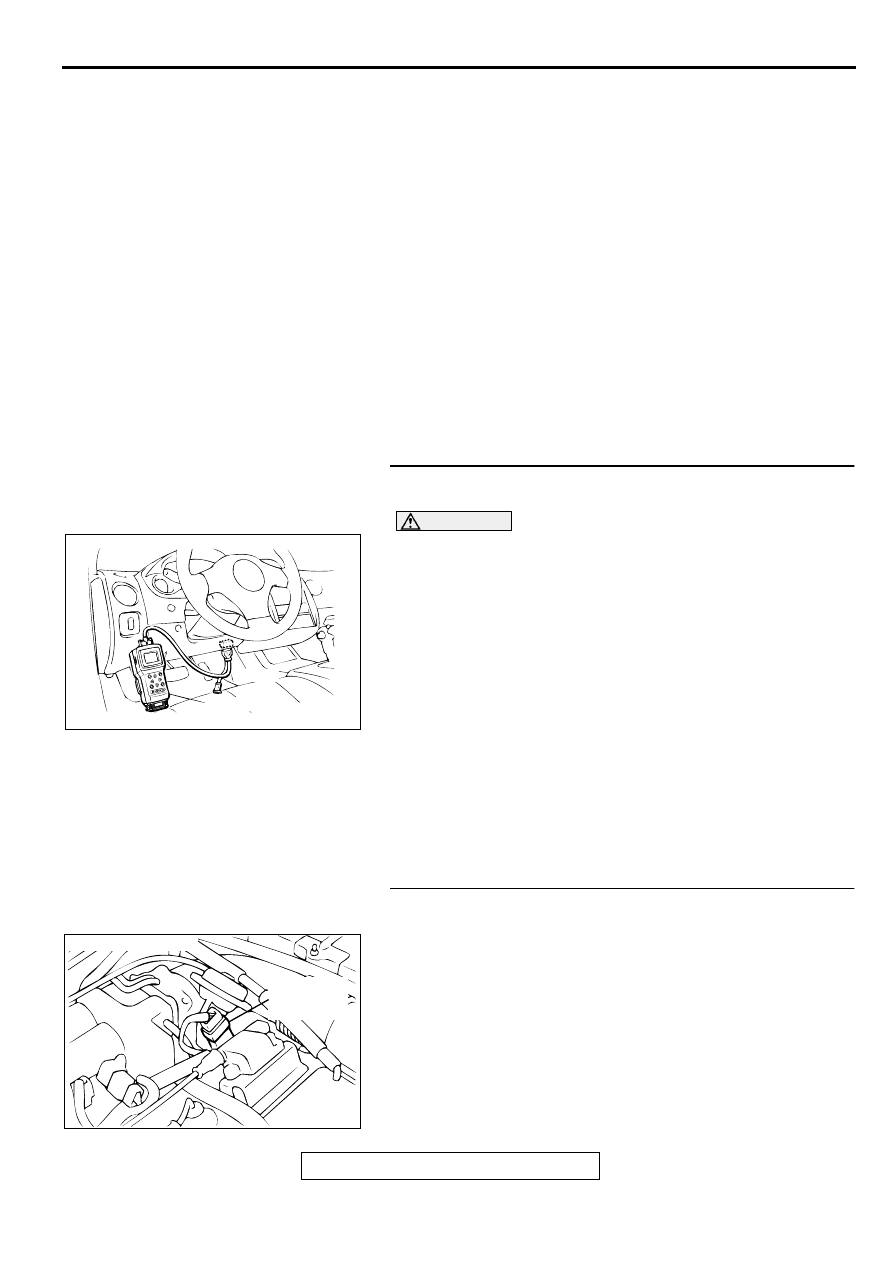
STEP 1. Using scan tool MB991502, check data list item 14:
Throttle Position Sensor.
CAUTION
To prevent damage to scan tool MB991502, always turn the
ignition switch to the "LOCK" (OFF) position before
connecting or disconnecting scan tool MB991502.
(1) Connect scan tool MB991502 to the data link connector.
(2) Turn the ignition switch to the "ON" position.
(3) Set scan tool MB991502 to the data reading mode for item
14, Throttle Position Sensor.
•
With the throttle valve in the idle position, voltage should
be between 0.535 and 0.735 volts.
•
With the throttle valve in the full-open position, voltage
should be between 4.5 and 5.5 volts.
(4) Turn the ignition switch to the "LOCK" (OFF) position.
Q: Is the sensor operating properly?
YES : It can be assumed that this malfunction is intermittent.
Refer to GROUP 00, How to Use Troubleshooting/
Inspection Service Points (
NO : Go to Step 2.
STEP 2. Check connector B-07 at throttle position sensor
for damage.
Q: Is the connector in good condition?
YES : Go to Step 3.
NO : Repair or replace it. Refer to GROUP 00E, Harness
Connector Inspection (
). Then go to Step 14.
AKX01177
16 PIN
MB991502
AB
ACX02472
CONNECTOR : B-07
THROTTLE
POSITION
SENSOR
AE
MULTIPORT FUEL INJECTION (MFI) DIAGNOSIS
TSB Revision
MULTIPORT FUEL INJECTION (MFI) <2.4L ENGINE>
13A-92
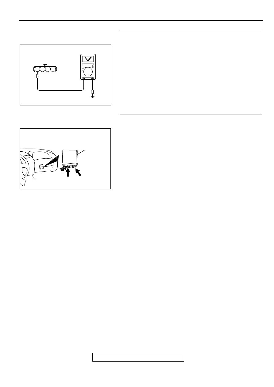
STEP 3. Check the sensor supply voltage at throttle
position sensor harness side connector B-07.
(1) Disconnect the connector B-07 and measure at the harness
side.
(2) Turn the ignition switch to the "ON" position.
(3) Measure the voltage between terminal 4 and ground.
•
Voltage should be between 4.8 and 5.2 volts.
(4) Turn the ignition switch to the "LOCK" (OFF) position.
Q: Is the voltage normal?
YES : Go to Step 6.
NO : Go to Step 4.
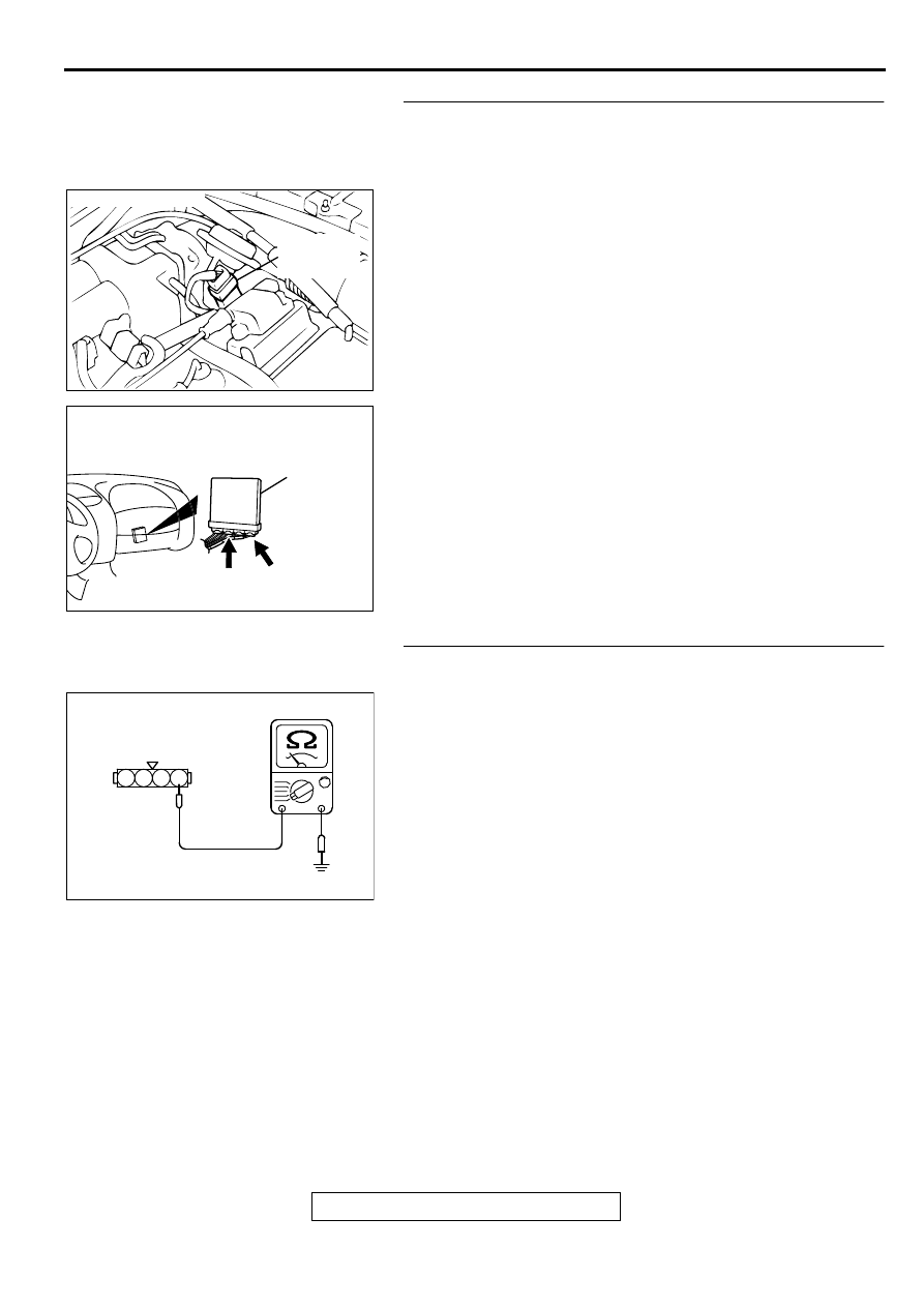
STEP 4. Check connector C-60 at ECM <M/T> or connector
C-54 at PCM <A/T> for damage.
Q: Is the connector in good condition?
YES : Go to Step 5.
NO : Repair or replace it. Refer to GROUP 00E, Harness
Connector Inspection (
). Then go to Step 14.
AK000236 AB
B-07 HARNESS
SIDE CONNECTOR
4 3 2 1
AK000280
C-54
C-60
ECM<M/T>
OR
PCM<A/T>
CONNECTORS:C-60<M/T>,C-54<A/T>
BB
MULTIPORT FUEL INJECTION (MFI) DIAGNOSIS
TSB Revision
MULTIPORT FUEL INJECTION (MFI) <2.4L ENGINE>
13A-93
STEP 5. Check for open circuit and short circuit to ground
between throttle position sensor connector B-07 terminal 4
and ECM connector C-60 terminal 81 <M/T> or PCM
connector C-54 terminal 46 <A/T>.
Q: Is the harness wire in good condition?
YES : Replace the ECM or PCM. Then go to Step 14.
NO : Repair it. Then go to Step 14.
STEP 6. Check the continuity at throttle position sensor
harness side connector B-07.
(1) Disconnect the connector B-07 and measure at the harness
side.
(2) Measure the continuity between terminal 1 and ground.
•
Should be less than 2 ohm.
Q: Is the continuity normal?
YES : Go to Step 9.
NO : Go to Step 7.
ACX02472
CONNECTOR : B-07
THROTTLE
POSITION
SENSOR
AE
AK000280
C-54
C-60
ECM<M/T>
OR
PCM<A/T>
CONNECTORS:C-60<M/T>,C-54<A/T>
BB
AK000237AB
B-07 HARNESS
SIDE CONNECTOR
4 3 2 1
MULTIPORT FUEL INJECTION (MFI) DIAGNOSIS
TSB Revision
MULTIPORT FUEL INJECTION (MFI) <2.4L ENGINE>
13A-94
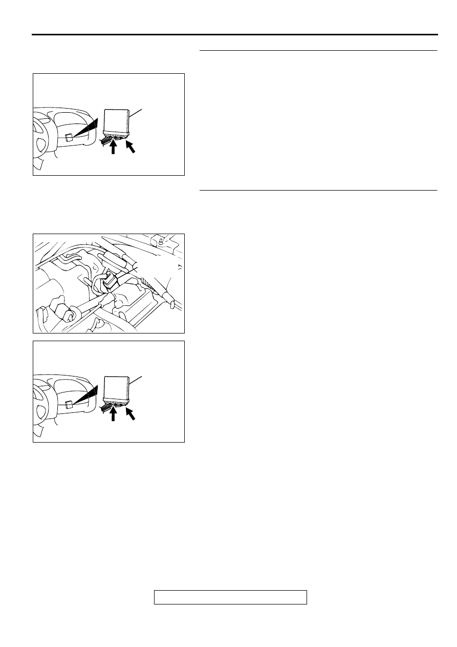
STEP 7. Check connector C-60 at ECM <M/T> or connector
C-54 at PCM <A/T> for damage.
Q: Is the connector in good condition?
YES : Go to Step 8.
NO : Repair or replace it. Refer to GROUP 00E, Harness
Connector Inspection (
). Then go to Step 14.
STEP 8. Check for open circuit and harness damage
between throttle position sensor connector B-07 terminal 1
and ECM connector C-60 terminal 92 <M/T> or PCM
connector C-54 terminal 57 <A/T>.
Q: Is the harness wire in good condition?
YES : Replace the ECM or PCM. Then go to Step 14.
NO : Repair it. Then go to Step 14.
AK000280
C-54
C-60
ECM<M/T>
OR
PCM<A/T>
CONNECTORS:C-60<M/T>,C-54<A/T>
BB
ACX02472
CONNECTOR : B-07
THROTTLE
POSITION
SENSOR
AE
AK000280
C-54
C-60
ECM<M/T>
OR
PCM<A/T>
CONNECTORS:C-60<M/T>,C-54<A/T>
BB
Нет комментариевНе стесняйтесь поделиться с нами вашим ценным мнением.
Текст