Mitsubishi Eclipse / Eclipse Spyder (2000-2002). Service and repair manual — part 180
MULTIPORT FUEL INJECTION (MFI) DIAGNOSIS
TSB Revision
MULTIPORT FUEL INJECTION (MFI) <2.4L ENGINE>
13A-419
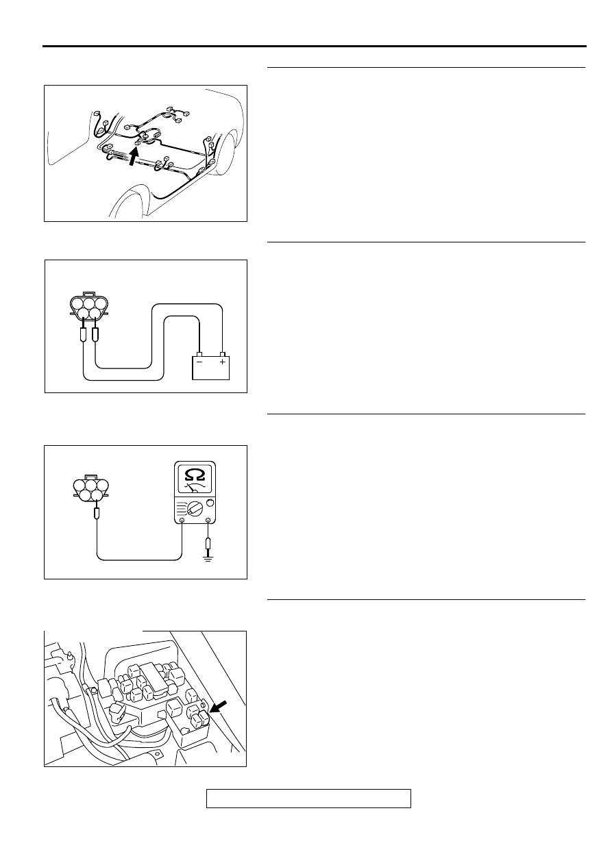
STEP 2. Check connector D-17 at fuel pump for damage.
Q: Is the connector in good condition?
YES : Go to Step 3.
NO : Repair or replace it. Refer to GROUP 00E, Harness
Connector Inspection (
). Then confirm that
the malfunction symptom is eliminated.
STEP 3 Check the fuel pump operation.
(1) Disconnect fuel pump connector D-17.
(2) Use jumper wires to connect fuel pump connector terminal
5 to the positive battery terminal and terminal 4 to the
negative battery terminal.
•
An operating sound of the fuel pump should be heard.
Q: Is the fuel pump operating properly?
YES : Go to Step 4.
NO : Replace the fuel pump Then confirm that the
malfunction symptom is eliminated.
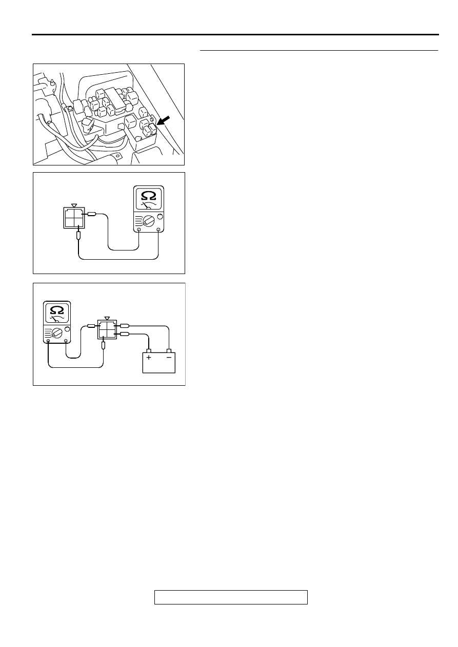
STEP 4. Check the continuity at fuel pump harness side
connector D-17.
(1) Disconnect the connector D-17 and measure at the harness
side.
(2) Check for the continuity between terminal 4 and ground.
•
Should be less than 2 ohm.
Q: Is the continuity normal?
YES : Go to Step 5.
NO : Repair harness wire damage between fuel pump
connector D-17 terminal 4 and ground because of
open circuit or harness damage. Then confirm that
the malfunction symptom is eliminated.
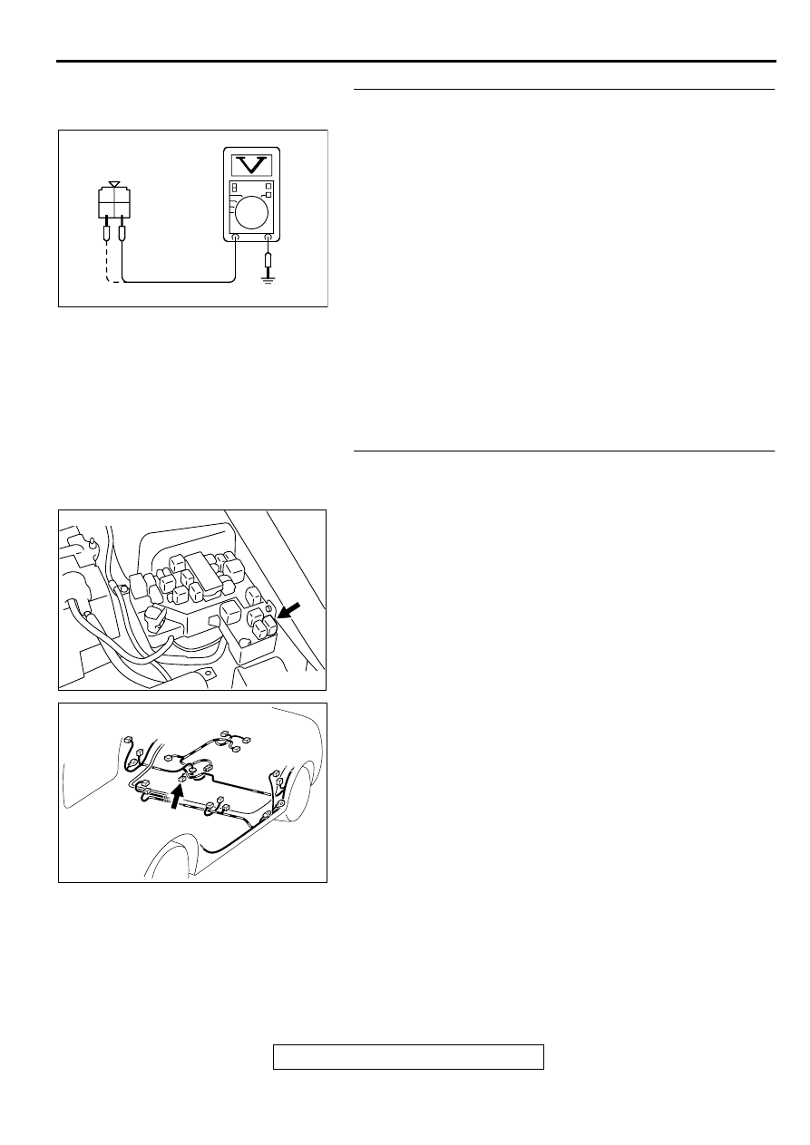
STEP 5. Check connector A-20X at fuel pump relay for
damage.
Q: Is the connector in good condition?
YES : Go to Step 6.
NO : Repair or replace it. Refer to GROUP 00E, Harness
Connector Inspection (
). Then confirm that
the malfunction symptom is eliminated.
AK000734AC
CONNECTOR:D-17
AKX01439
FUEL PUMP SIDE
CONNECTOR
AB
1 2 3
4 5
AKX01440AC
1
2
3
4
5
D-17 HARNESS
SIDE CONNECTOR
AK000360AB
CONNECTOR : A-20X
MULTIPORT FUEL INJECTION (MFI) DIAGNOSIS
TSB Revision
MULTIPORT FUEL INJECTION (MFI) <2.4L ENGINE>
13A-420
STEP 6. Check the fuel pump relay
(1) Remove the fuel pump relay.
(2) Check for continuity between the fuel pump relay terminals
2 and 4.
•
There should be continuity (approximately 70
Ω
)
(3) Use jumper wires to connect fuel pump relay terminal 4 to
the positive battery terminal and terminal 2 to the negative
battery terminal.
(4) Check the continuity between the fuel pump relay terminals
1 and 3 while connecting and disconnecting the jumper
wire at the negative battery terminal.
•
Should be less than 2 ohm. (Negative battery terminal
connected)
•
Should be open loop. (Negative battery terminal
disconnected)
(5) Install the fuel pump relay.
Q: Is the resistance normal?
YES : Go to Step 7.
NO : Replace the fuel pump relay. Then confirm that the
malfunction symptom is eliminated
AK000360AB
CONNECTOR : A-20X
AK000369AC
FUEL PUMP RELAY
SIDE CONNECTOR
1 2
3 4
AK000370AC
FUEL PUMP RELAY
SIDE CONNECTOR
1 2
3 4
MULTIPORT FUEL INJECTION (MFI) DIAGNOSIS
TSB Revision
MULTIPORT FUEL INJECTION (MFI) <2.4L ENGINE>
13A-421
STEP 7. Check the power supply voltage at fuel pump relay
connector A-20X.
(1) Disconnect the connector A-20X and measure at the
harness side.
(2) Turn the ignition switch to the "ON" position.
(3) Measure the voltage between terminal 3, 4 and ground.
•
Voltage should be battery positive voltage.
(4) Turn the ignition switch to the "LOCK" (OFF) position.
Q: Is the voltage normal?
YES : Go to Step 8.
NO : Check harness connectors C-07, C-89 and C-101 at
intermediate connector for damage, and repair or
replace as required. Refer to, GROUP 00E, Harness
Connector Inspection (
). If intermediate
connectors are in good condition, repair harness wire
between ignition switch connector C-87 terminal 2
and fuel pump relay connector A-20X terminal 3, 4
because of open circuit. Then confirm that the
malfunction symptom is eliminated.
STEP 8. Check for open circuit and short circuit to ground
and harness damage between fuel pump relay connector
A-20X terminal 1 and fuel pump connector D-17 terminal 5.
NOTE: Check harness after checking intermediate connectors
C-28 and C-90. If intermediate connectors are damaged, repair
or replace them. After to GROUP 00E, Harness Connector
Inspection (
). Then check that the malfunction is
eliminated.
Q: Is the harness wire in good condition?
YES : Go to Step 9.
NO : Repair it. Then confirm that the malfunction symptom
is eliminated.
AKX01441
A-20X HARNESS
SIDE CONNECTOR
1
2
3
4
AC
AK000360AB
CONNECTOR : A-20X
AK000734AC
CONNECTOR:D-17
MULTIPORT FUEL INJECTION (MFI) DIAGNOSIS
TSB Revision
MULTIPORT FUEL INJECTION (MFI) <2.4L ENGINE>
13A-422
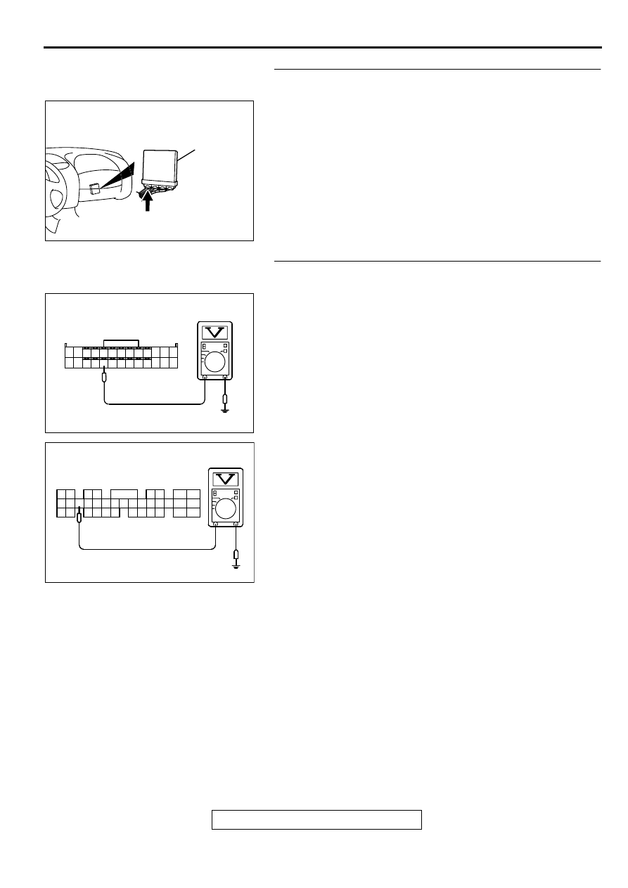
STEP 9. Check connector C-49 at ECM <M/T> or connector
C-50 at PCM <A/T> for damage.
Q: Is the connector in good condition?
YES : Go to Step 10.
NO : Repair or replace it. Refer to GROUP 00E, Harness
Connector Inspection (
). Then confirm that
the malfunction symptom is eliminated.
STEP 10. Check the power supply voltage at ECM
connector C-49 <M/T> or PCM connector C-50 <A/T>.
(1) Disconnect the connector C-49 <M/T> or C-50 <A/T> and
measure at the harness side.
(2) Turn the ignition switch to the "ON" position.
(3) Measure the voltage between terminal 22 <M/T> or 21 <A/
T> and ground.
•
Voltage should be battery positive voltage.
(4) Turn the ignition switch to the "LOCK" (OFF) position.
Q: Is the voltage normal?
YES : Replace the ECM or PCM. Then confirm that the
malfunction symptom is eliminated.
NO : Repair harness wire between fuel pump relay
connector A-20X terminal 2 and ECM connector C-49
terminal 22 <M/T> or PCM connector C-50 terminal
21 <A/T> because of open circuit. Then confirm that
the malfunction symptom is eliminated.
AK000280
C-49,C-50
ECM<M/T>
OR
PCM<A/T>
CONNECTORS:C-49<M/T>,C-50<A/T>
BC
AK000408AC
1
2
3
4
5
6
7
8
9
10
11
12
13
14
15
16
17
18
19
20
21
22
23
24
25
26
<M/T>
C-49 HARNESS
SIDE CONNECTOR
AK000409
AK000409 AG
1
2
3
4
5
6
7
8
9
10
11
12
13
14
15
16
17
18
19
20
21
22
23
24
25
26
27
28
29
30
31
32
33
34
35
<A/T>
C-50 HARNESS
SIDE CONNECTOR
Нет комментариевНе стесняйтесь поделиться с нами вашим ценным мнением.
Текст