Mitsubishi Eclipse / Eclipse Spyder (2000-2002). Service and repair manual — part 133
MULTIPORT FUEL INJECTION (MFI) DIAGNOSIS
TSB Revision
MULTIPORT FUEL INJECTION (MFI) <2.4L ENGINE>
13A-231
DIAGNOSIS
Required Special Tools
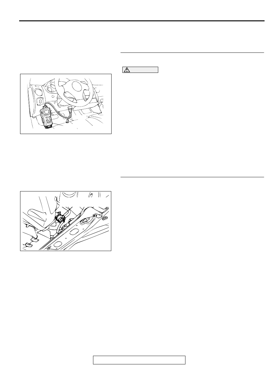
MB991502: Scan Tool (MUT-II)
STEP 1. Using scan tool MB991502, check actuator test
item 29: Evaporative Emission Ventilation Solenoid.
CAUTION
To prevent damage to scan tool MB991502, always turn the
ignition switch to the "LOCK" (OFF) position before
connecting or disconnecting scan tool MB991502.
(1) Connect scan tool MB991502 to the data link connector.
(2) Turn the ignition switch to the "ON" position.
(3) Set scan tool MB991502 to the actuator test mode for item
29, Evaporative emission ventilation solenoid.
•
An operation sound should be heard and vibration
should be felt when the evaporative emission ventilation
solenoid is operated.
(4) Turn the ignition switch to the "LOCK" (OFF) position.
Q: Is the solenoid operating properly?
YES : It can be assumed that this malfunction is intermittent.
Refer to GROUP 00, How to Use Troubleshooting/
Inspection Service Points (
NO : Go to Step 2.
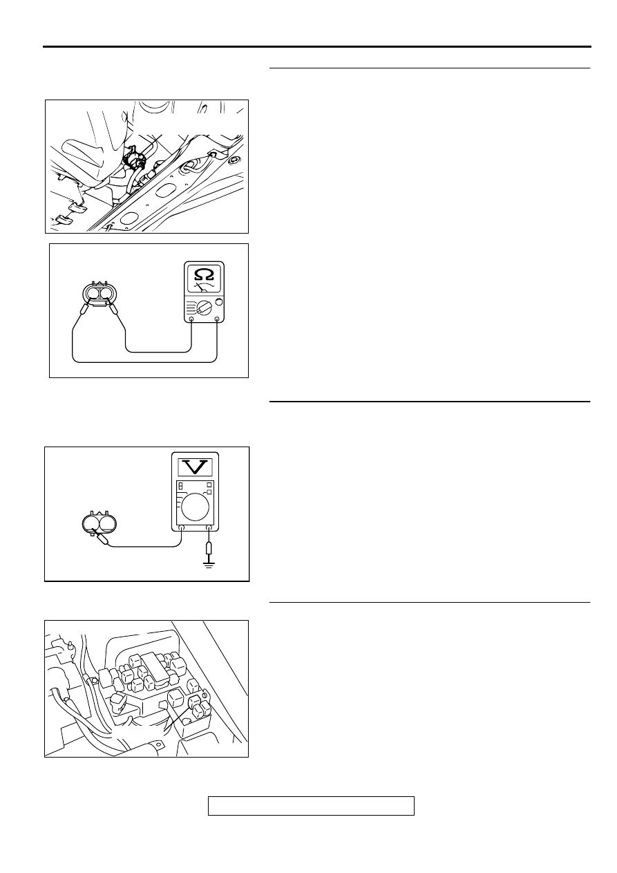
STEP 2 Check connector D-10 at the evaporative emission
ventilation solenoid for damage.
Q: Is the connector in good condition?
YES : Go to Step 3.
NO : Repair or replace it. Refer to GROUP 00E, Harness
Connector Inspection (
). Then go to Step 12.
AKX01177
16 PIN
MB991502
AB
ACX02516
CONNECTOR:D-10
EVAPORATIVE EMISSION
VENTILATION SOLENOID
AJ
MULTIPORT FUEL INJECTION (MFI) DIAGNOSIS
TSB Revision
MULTIPORT FUEL INJECTION (MFI) <2.4L ENGINE>
13A-232
STEP 3 Check the evaporative emission ventilation
solenoid.
(1) Disconnect the evaporative emission ventilation solenoid
connector D-10.
(2) Measure the resistance between evaporative emission
ventilation solenoid side connector terminal 1 and 2.
Standard value: 17
−
21
Ω
[at 20
°
C (68
°
F)]
Q: Is the resistance at the standard value?
YES : Go to Step 4.
NO : Replace the over vent valve module. Then go to Step
12.
STEP 4. Check the power supply voltage at evaporative
emission ventilation solenoid harness side connector D-
10.
(1) Disconnect the connector D-10 and measure at the harness
side.
(2) Turn the ignition switch to the "ON" position.
(3) Measure the voltage between terminal 2 and ground.
•
Voltage should be battery positive voltage.
(4) Turn the ignition switch to the "LOCK" (OFF) position.
Q: Is the voltage normal?
YES : Go to Step 6.
NO : Go to Step 5.
STEP 5. Check connector A-21X at MFI relay for damage.
Q: Is the connector in good condition?
YES : Check connectors D-16, C-90 and C-28 at
intermediate connector for damage, and repair or
replace as required. Refer to GROUP 00E, Harness
Connector Inspection (
). If intermediate
connectors are in good condition, repair harness wire
between MFI relay connector A-21X terminal 1 and
evaporative emission ventilation solenoid connector
D-10 terminal 2 because of open circuit or short circuit
to ground. Then go to Step 12.
NO : Repair or replace it. Refer to GROUP 00E, Harness
Connector Inspection (
). Then go to Step 12.
ACX02516
CONNECTOR:D-10
EVAPORATIVE EMISSION
VENTILATION SOLENOID
AJ
AK000004
2
1
EVAPORATIVE EMISSION
VENTILATION SOLENOID
AB
AKX01502
1
2
D-10 HARNESS
SIDE CONNECTOR
AI
AK000226
AK000226AB
CONNECTOR : A-21X
MFI RELAY
MULTIPORT FUEL INJECTION (MFI) DIAGNOSIS
TSB Revision
MULTIPORT FUEL INJECTION (MFI) <2.4L ENGINE>
13A-233
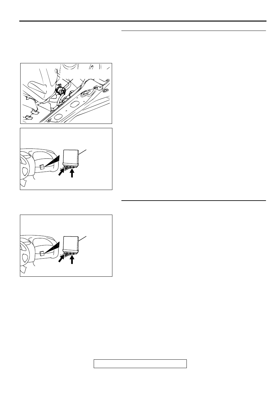
STEP 6. Check the power supply voltage at ECM connector
C-56 <M/T> or PCM connector C-50 <A/T> by backprobing
(1) Do not disconnect the connector C-56 <M/T> or C-50 <A/
T>.
(2) Turn the ignition switch to the "ON" position.
(3) Measure the voltage between terminal 55 <M/T> or 35 <A/
T> and ground by backprobing.
•
Voltage should be battery positive voltage.
(4) Turn the ignition switch to the "LOCK" (OFF) position.
Q: Is the voltage normal?
YES : Go to Step 9.
NO : Go to Step 7.
STEP 7. Check connector C-56 at ECM <M/T> or connector
C-50 at PCM <A/T> for damage.
Q: Is the connector in good condition?
YES : Go to Step 8.
NO : Repair or replace it. Refer to GROUP 00E, Harness
Connector Inspection (
). Then go to Step 12.
AK000302
<M/T>
C-56 CONNECTOR
HARNESS SIDE VIEW
51 52 53 54 55 56
57 58 59 60 61 62
AC
AK000303
1
2
3 4
5 6
7 8
9 10 11 1213 141516 17 1819 20 21 2223
24 25
2627 2829
30 3132 33
3435
AD
C-50 CONNECTOR
HARNESS SIDE VIEW
<A/T>
AK000280
C-49
C-56
ECM<M/T>
OR
PCM<A/T>
CONNECTORS:C-56<M/T>,C-50<A/T>
BG
MULTIPORT FUEL INJECTION (MFI) DIAGNOSIS
TSB Revision
MULTIPORT FUEL INJECTION (MFI) <2.4L ENGINE>
13A-234
STEP 8. Check for open circuit and short circuit to ground
between evaporative emission ventilation solenoid
connector D-10 terminal 1 and ECM connector C-56
terminal 55 <M/T> or PCM connector C-50 terminal 35 <A/
T>.
NOTE: Check harness after checking intermediate connectors
D-16, C-90 and C-28. If intermediate connectors are damaged,
repair or replace them. Refer to GROUP 00E, Harness
Connector Inspection (
). Then go to Step 12.
Q: Is the harness wire in good condition?
YES : Replace the ECM or PCM. Then go to Step 12.
NO : Repair it. Then go to Step 12.
STEP 9. Check connector C-56 at ECM <M/T> or connector
C-50 at PCM <A/T> for damage.
Q: Is the connector in good condition?
YES : Go to Step 10.
NO : Repair or replace it. Refer to GROUP 00E, Harness
Connector Inspection (
). Then go to Step 12.
ACX02516
CONNECTOR:D-10
EVAPORATIVE EMISSION
VENTILATION SOLENOID
AJ
AK000280
C-49
C-56
ECM<M/T>
OR
PCM<A/T>
CONNECTORS:C-56<M/T>,C-50<A/T>
BG
AK000280
C-49
C-56
ECM<M/T>
OR
PCM<A/T>
CONNECTORS:C-56<M/T>,C-50<A/T>
BG
Нет комментариевНе стесняйтесь поделиться с нами вашим ценным мнением.
Текст