Mitsubishi Eclipse / Eclipse Spyder (2000-2002). Service and repair manual — part 362
STARTING SYSTEM
TSB Revision
ENGINE ELECTRICAL
16-25
INSPECTION
M1162001100056
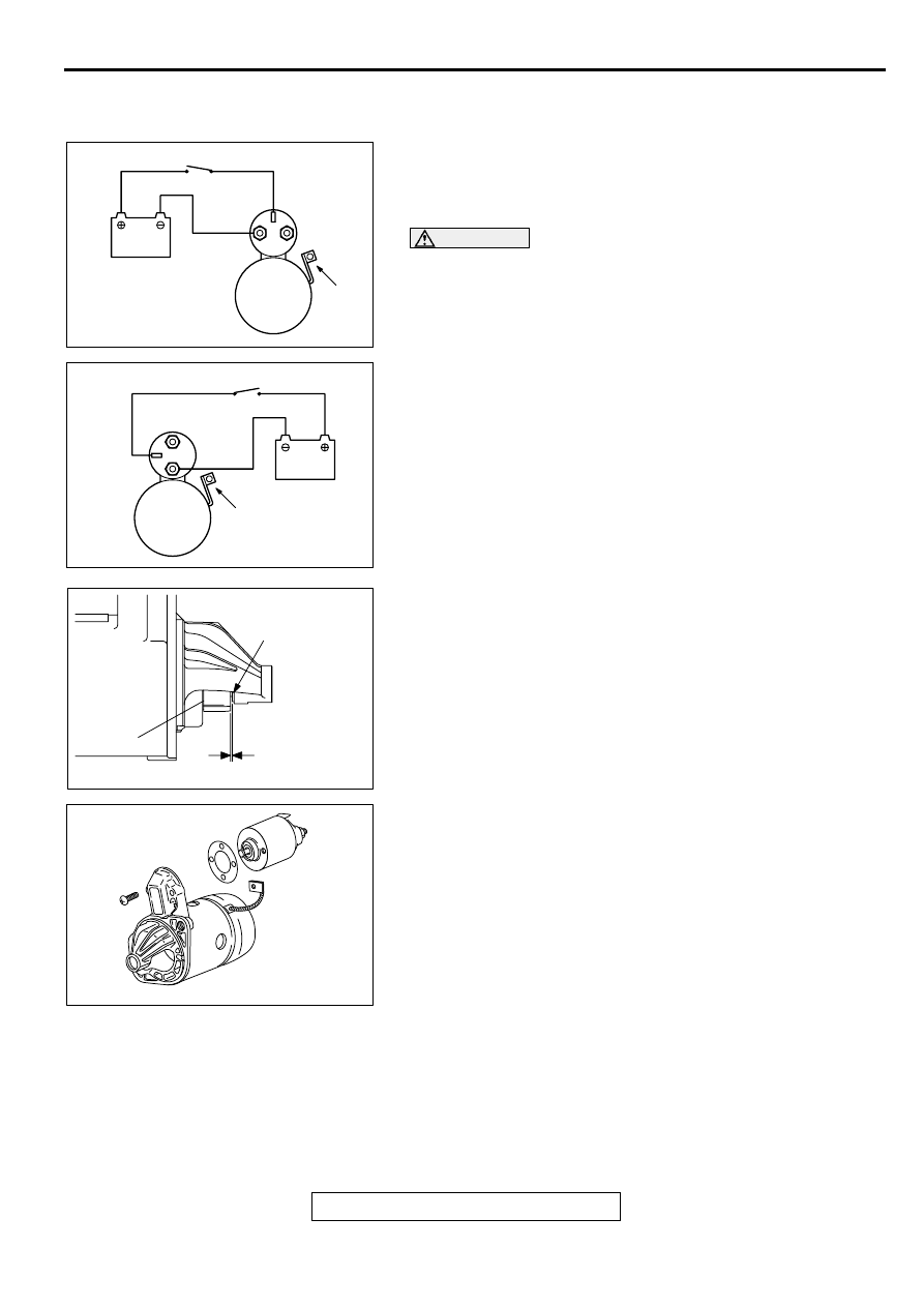
PINION GAP ADJUSTMENT
1. Disconnect the field coil wire from the M-terminal of the
magnetic switch.
2. Connect a 12-volt battery between the S-terminal and M-
terminal.
CAUTION
This test must be performed quickly (in less than 10
seconds) to prevent the coil from burning.
3. Set the switch to "ON," and the pinion will move out.
4. Check the pinion-to-stopper clearance (pinion gap) with a
feeler gauge.
Standard value: 0.5
−
2.0 mm (0.02
−
0.07 inch)
5. If the pinion gap is out of specification, adjust by adding or
removing gasket(s) between the magnetic switch and front
bracket.
AKX01238
<2.4L ENGINE>
B
M
S
BATTERY
SWITCH
STARTER
MOTOR
WIRE
AC
AKX01239
<3.0L ENGINE>
B
M
S
BATTERY
SWITCH
STARTER
MOTOR
WIRE
AB
AKX00198
STOPPER
PINION GAP
PINION
AB
AKX00199
STARTING SYSTEM
TSB Revision
ENGINE ELECTRICAL
16-26
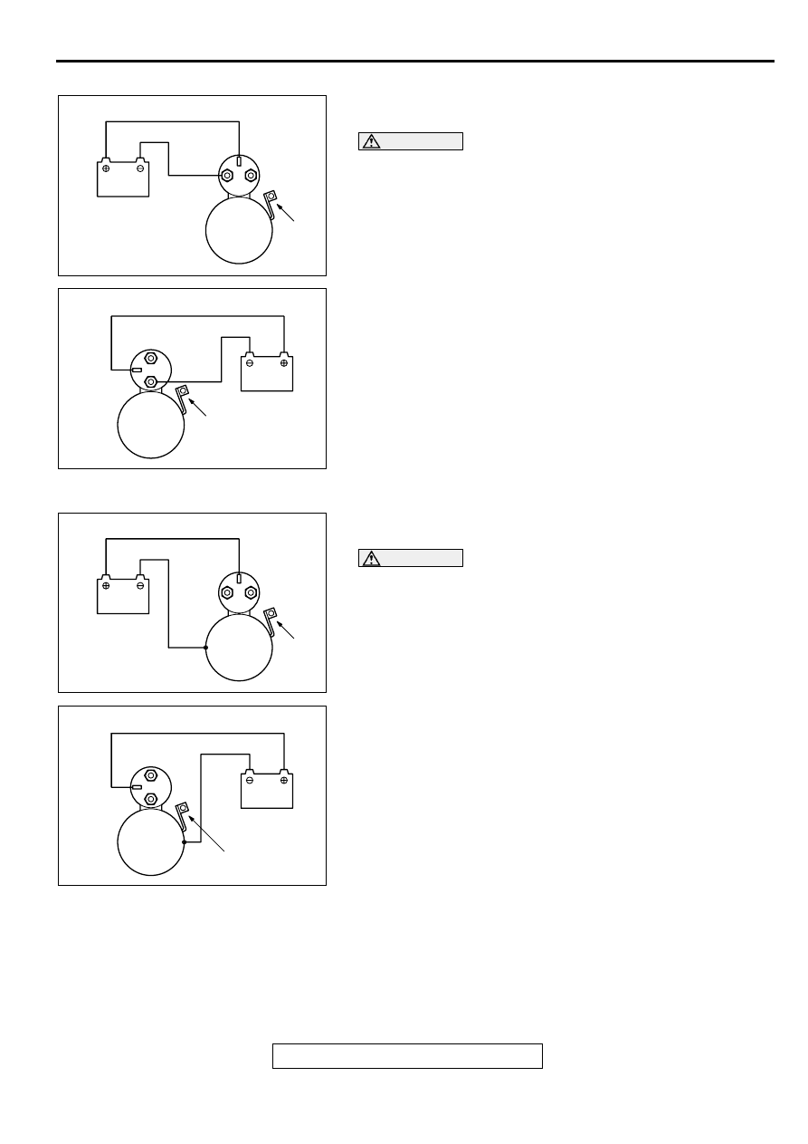
MAGNETIC SWITCH PULL-IN TEST
1. Disconnect the field coil wire from the M-terminal of the
magnetic switch.
CAUTION
This test must be performed quickly (in less than 10
seconds) to prevent the coil from burning.
2. Connect a 12-volt battery between the S-terminal and M-
terminal.
3. If the pinion moves out, the pull-in coil is good. If it doesn't,
replace the magnetic switch.
MAGNETIC SWITCH HOLD-IN TEST
1. Disconnect the field coil wire from the M-terminal of the
magnetic switch.
CAUTION
This test must be performed quickly (in less than 10
seconds) to prevent the coil from burning.
2. Connect a 12-volt battery between the S-terminal and body.
3. Manually pull out the pinion as far as the pinion stopper
position.
4. If the pinion remains out, everything is operating properly. If
the pinion moves in, the hold-in circuit is open. Replace the
magnetic switch.
AKX01242
<2.4L ENGINE>
S
B
M
BATTERY
STARTER
MOTOR
WIRE
AB
AKX01243
<3.0L ENGINE>
B
M
S
BATTERY
STARTER
MOTOR
WIRE
AB
AKX01244
<2.4L ENGINE>
S
B
M
BATTERY
STARTER
MOTOR
WIRE
AB
AKX01245
<3.0L ENGINE>
B
M
S
BATTERY
STARTER
MOTOR
WIRE
AB
STARTING SYSTEM
TSB Revision
ENGINE ELECTRICAL
16-27
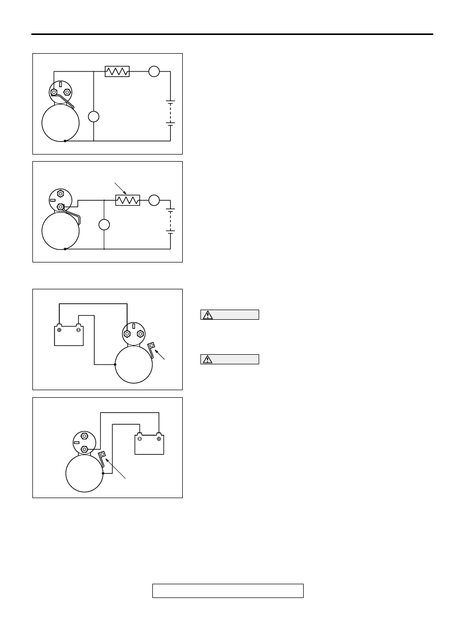
FREE RUNNING TEST
1. Place the starter motor in a vise equipped with soft jaws and
connect a fully-charged 12-volt battery to the starter motor
as follows:
2. Connect a test ammeter (100-ampere scale) and carbon pile
rheostat in series between the positive battery terminal and
starter motor terminal.
3. Connect a voltmeter (15-volt scale) across the starter motor.
4. Rotate carbon pile to full-resistance position.
5. Connect the battery cable from the negative battery terminal
to the starter motor body.
6. Adjust the rheostat until the battery positive voltage shown
by the voltmeter is 11 V.
7. Confirm that the maximum amperage is within the
specifications and that the starter motor turns smoothly and
freely.
Current: maximum 90 Amps
MAGNETIC SWITCH RETURN TEST
1. Disconnect the field coil wire from the M-terminal of the
magnetic switch.
CAUTION
This test must be performed quickly (in less than 10
seconds) to prevent the coil from burning.
2. Connect a 12-volt battery between the M-terminal and body.
WARNING
Be careful not to get your fingers caught when pulling
out the pinion.
3. Pull the pinion out and release. If the pinion quickly returns
to its original position, everything is operating properly. If it
doesn't, replace the magnetic switch.
AKX01246
<2.4L ENGINE>
S
M
B
AMMETER
CARBON-PILE
RHEOSTAT
BATTERY
STARTER
MOTOR
VOLTMETER
AB
A
V
AKX01247
<3.0L ENGINE>
B
M
S
CARBON-PILE
RHEOSTAT
AMMETER
BATTERY
STARTER
MOTOR
VOLTMETER
AB
A
V
AKX01248
<2.4L ENGINE>
S
B
M
BATTERY
STARTER
MOTOR
WIRE
AB
AKX01249
<3.0L ENGINE>
B
M
S
BATTERY
STARTER
MOTOR
WIRE
AB
STARTING SYSTEM
TSB Revision
ENGINE ELECTRICAL
16-28
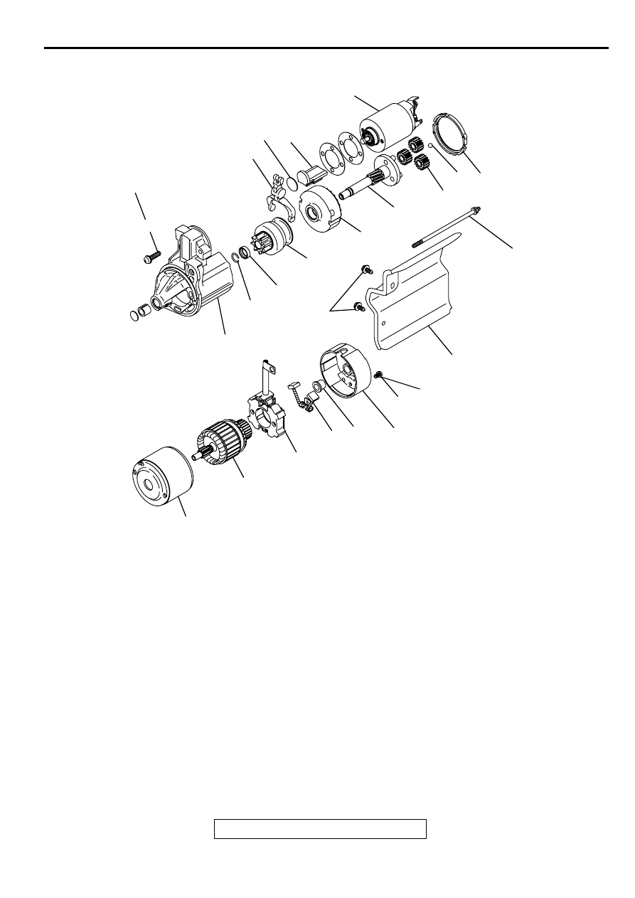
DISASSEMBLY AND ASSEMBLY
M1162001200042
AK000041
5.8 ± 1.6 N·m
52 ± 14 in-lb
2
23
18
19
5.8 ± 1.6 N·m
52 ± 14 in-lb
20
21
17
15
14
22
3
16
12 13
5.7 ± 1.5 N·m
51 ± 13 in-lb
3.4 ± 1.0 N·m
30 ± 9 in-lb
1
4
6
9
8
7
10
11
AB
DISASSEMBLY STEPS
1. COVER
2. SCREW
3. MAGNETIC SWITCH
4. SCREW
5. SCREW
6. REAR BRACKET
7. BRUSH HOLDER
8. BRUSH
9. REAR BEARING
<<A>>
10. ARMATURE
11. YOKE ASSEMBLY
<<A>>
12. BALL
13. PACKING A
14. PACKING B
15. PLATE
16. PLANETARY GEAR
17. LEVER
<<B>> >>A<<
18. SNAP RING
<<B>> >>A<<
19. STOP RING
20. OVERRUNNING CLUTCH
21. INTERNAL GEAR
22. PLANETARY GEAR HOLDER
23. FRONT BRACKET
DISASSEMBLY STEPS (Continued)
Нет комментариевНе стесняйтесь поделиться с нами вашим ценным мнением.
Текст