Mitsubishi Eclipse / Eclipse Spyder (2000-2002). Service and repair manual — part 363
STARTING SYSTEM
TSB Revision
ENGINE ELECTRICAL
16-29
DISASSEMBLY SERVICE POINTS
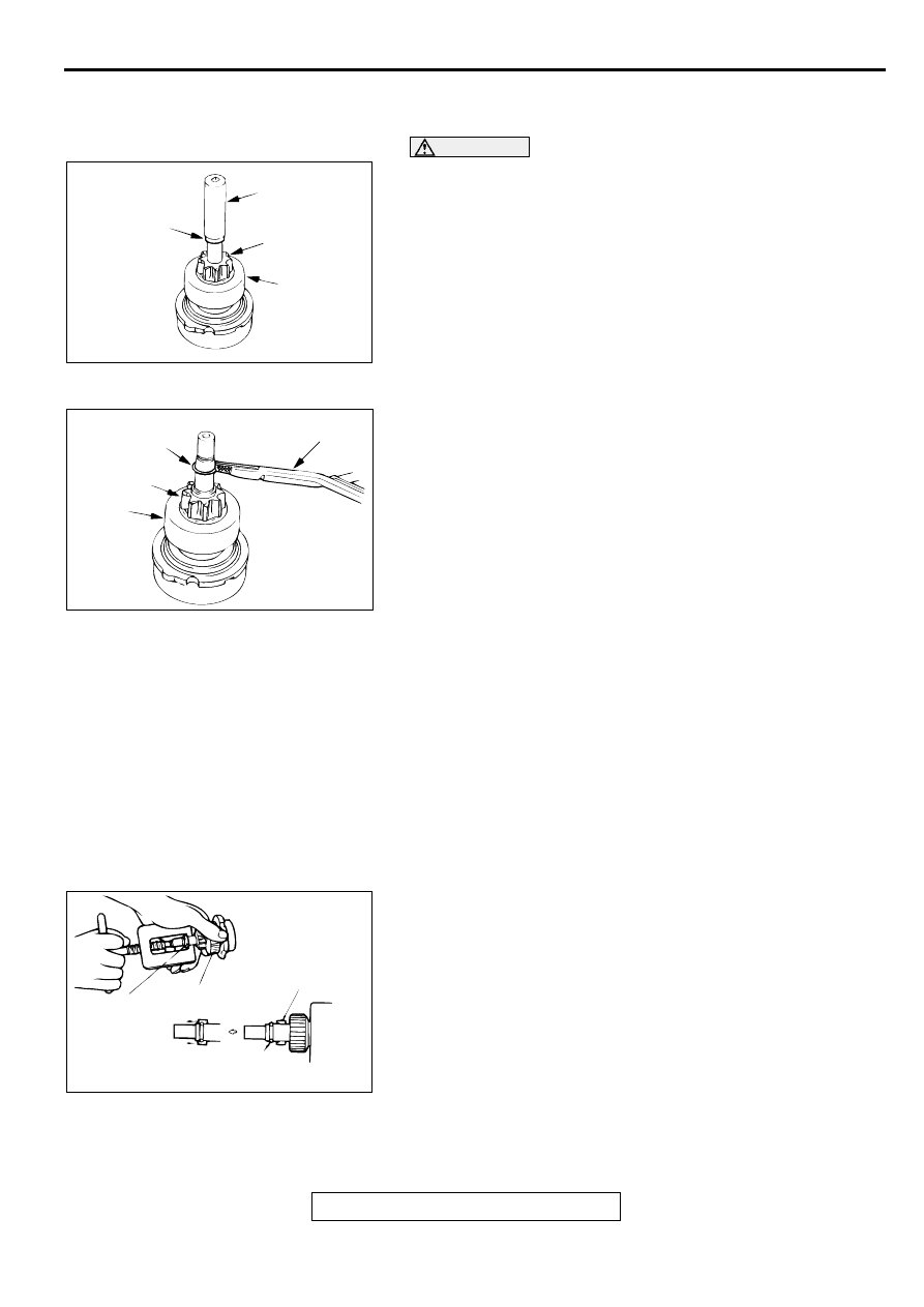
<<A>> ARMATURE AND BALL REMOVAL
CAUTION
When removing the armature, take care not to lose the ball
(which is used as a bearing) in the armature end.
<<B>> SNAP RING AND STOP RING REMOVAL
1. Press a long socket wrench of appropriate size to the stop
ring. Then tap the socket wrench to remove the stop ring to
the pinion gear side.
2. After removing the snap ring (by using snap-ring pliers),
remove the stop ring and the overrunning clutch.
STARTER MOTOR PART CLEANING
1. Do not immerse parts in cleaning solvent. Immersing the
yoke and field coil assembly and/or armature will damage
insulation. Wipe these parts with a shop towel only.
2. Do not immerse the drive unit in cleaning solvent.
Overrunning clutch is pre-lubricated at the factory and
solvent will wash lubrication from the clutch.
3. The drive unit may be cleaned with a brush moistened with
cleaning solvent and wiped dry with a shop towel.
ASSEMBLY SERVICE POINT
>>A<< STOP RING AND SNAP RING INSTALLATION
1. Using a suitable pulling tool, pull the overrunning clutch stop
ring over the snap ring.
AKX00370
SOCKET
STOP RING
PINION GEAR
OVERRUN-
NING
CLUTCH
AB
AKX00371
SNAP RING
PINION
GEAR
OVERRUN-
NING
CLUTCH
SNAP-RING
PLIERS
AB
AKX00372
STOP RING
OVERRUNNING
CLUTCH
SNAP RING
STOP
RING
AB
STARTING SYSTEM
TSB Revision
ENGINE ELECTRICAL
16-30
INSPECTION
M1162001300027
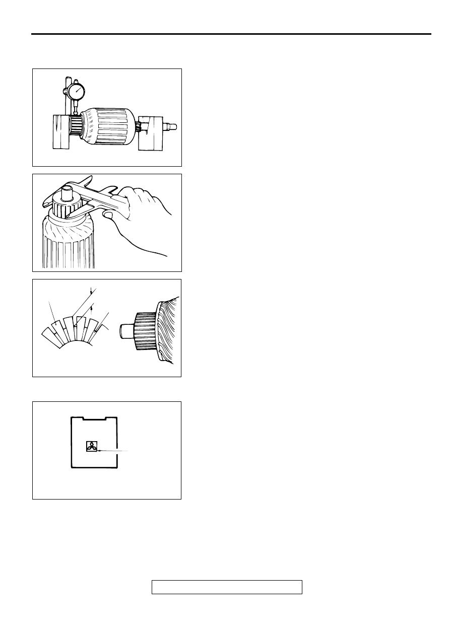
COMMUTATOR CHECK
1. Place the armature on a pair of V-blocks, and check the
deflection by using a dial gauge.
Standard value: 0.05 mm (0.002 inch)
Limit: 0.1 mm (0.004 inch)
2. Check the outer diameter of the commutator.
Standard value: 29.4 mm (1.16 inch)
Minimum limit: 28.8 mm (1.13 inch)
3. Check the depth of the undercut between segments.
Standard value: 0.5 mm (0.02 inch)
Minimum limit: 0.2 mm (0.008 inch)
BRUSH CHECK
1. Brushes that are worn beyond wear limit line, or oil-soaked,
should be replaced.
2. When replacing the ground brush, slide the brush from the
brush holder by prying the retaining spring back.
AKX00373
AKX00374
AKX00375
SEGMENT
UNDERCUT
MICA
AB
AKX00377
WEAR LIMIT
LINE
AB
STARTING SYSTEM
TSB Revision
ENGINE ELECTRICAL
16-31
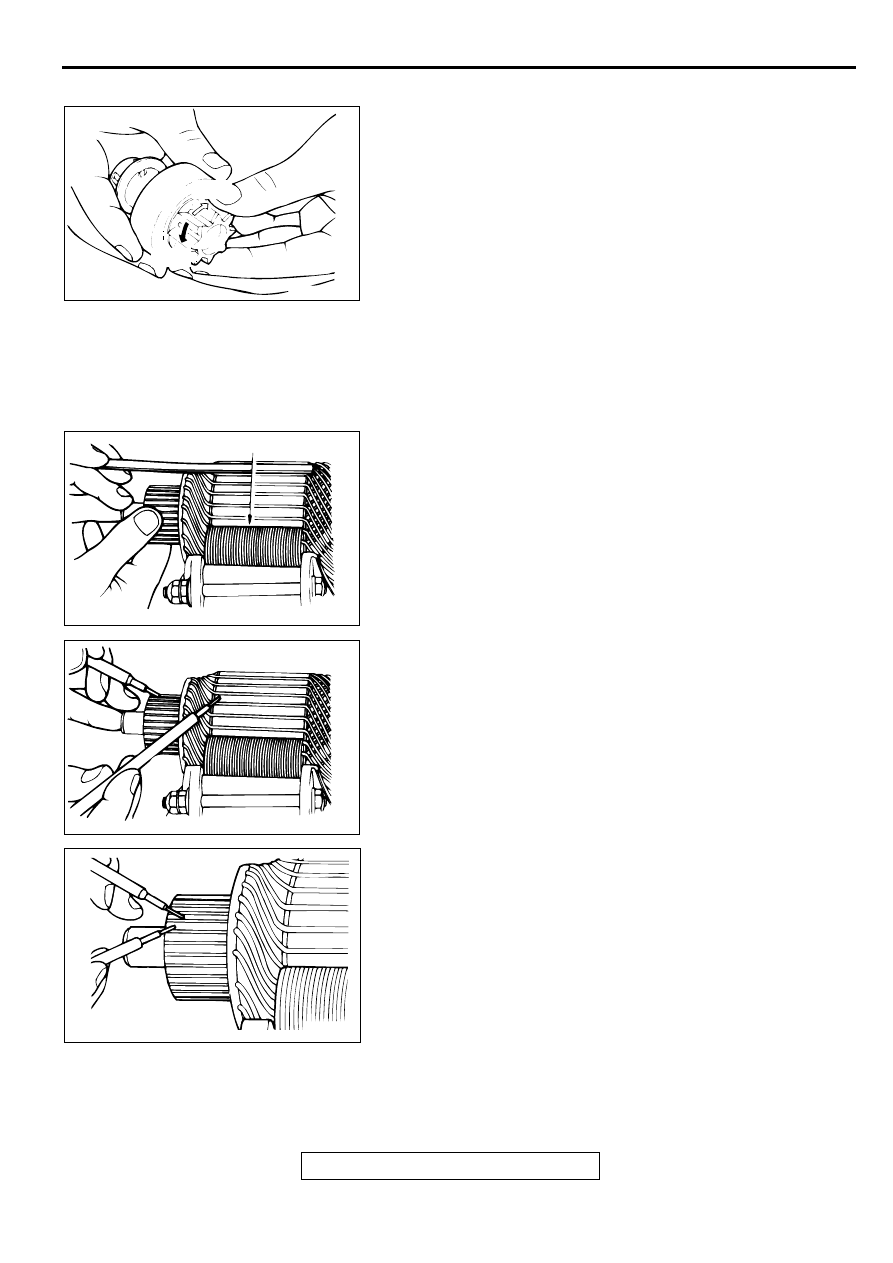
OVERRUNNING CLUTCH CHECK
1. While holding the clutch housing, rotate the pinion. The drive
pinion should rotate smoothly in one direction, but should
not rotate in opposite direction. If the clutch does not
function properly, replace the overrunning clutch assembly.
2. Inspect the pinion for wear or burrs. If the pinion is worn or
burred, replace the overrunning clutch assembly. If the
pinion is damaged, also inspect the ring gear for wear or
burrs.
FRONT AND REAR BRACKET BUSHING CHECK
Inspect the bushing for wear or burrs. If the bushing is worn or
burred, replace the front bracket assembly or rear bracket
assembly.
ARMATURE CHECK
1. Check that the armature coil is not grounded.
2. Place the armature in a growler.
3. Hold a thin steel blade parallel and just above while rotating
the armature slowly in the growler. A shorted armature will
cause a blade to vibrate and be attracted to the core.
Replace the shorted armature.
4. Check the insulation between the armature coil cores and
the commutator segments. They are normal if there is no
continuity.
5. Check for continuity between the segments. The condition is
normal if there is continuity.
AKX00378
FREE
LOCK
AB
AKX00379
GROWLER
AB
AKX00380
AKX00381
IGNITION SYSTEM
TSB Revision
ENGINE ELECTRICAL
16-32
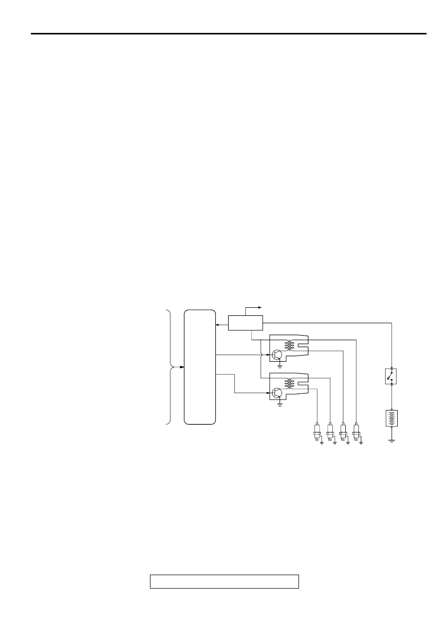
IG N ITIO N SYSTEM
GENERAL DESCRIPTION
M1163000100045
<2.4L Engine>
This system is provided with two ignition coils (A and
B) with built-in ignition power transistors for the
number 1 and number 4 cylinders, and number 2 and
number 3 cylinders respectively.
Interruption of the primary current flowing in the
primary side of ignition coil A generates a high
voltage in the secondary side of ignition coil A.
The high voltage thus generated is applied to the
spark plugs of number 1 and number 4 cylinders to
generate sparks. At the time that the sparks are
generated at both spark plugs, if one cylinder is at
the compression stroke, the other cylinder is at the
exhaust stroke, so that ignition of the compressed
air/fuel mixture occurs only for the cylinder which is
at the compression stroke.
In the same way, when the primary current flowing in
ignition coil B is interrupted, the high voltage thus
generated is applied to the spark plugs of number 2
and number 3 cylinders.
The engine control module controls the two ignition
power transistors to turn them alternately ON and
OFF. This causes the primary currents in the ignition
coils to be alternately interrupted and allowed to flow
to fire the cylinders in the order 1
−
3
−
4
−
2.
The engine control module determines which ignition
coil should be controlled by means of the signals
from the camshaft position sensor which is
incorporated in the camshaft and from the crankshaft
position sensor which is incorporated in the
crankshaft.
It also detects the crankshaft position in order to
provide ignition at the most appropriate timing in
response to the engine operation conditions.
When the engine is cold or operated at high
altitudes, the ignition timing is slightly advanced to
provide optimum performance.
<3.0L Engine>
Interruption of the primary current flowing in the
primary side of the ignition coil generates high
voltage in the secondary side of the ignition coil. The
high voltage thus generated is directed by the
distributor to the applicable spark plug. The engine
firing order is 1
−
2
−
3
−
4
−
5
−
6 cylinders.
On application of high voltage, the spark plug
generates a spark to ignite the compressed air fuel
mixture in the combustion chamber.
The engine control module makes and breaks the
primary current of the ignition coil to regulate the
ignition timing.
AKX01212
INTAKE AIR TEMPERATURE SENSOR
BAROMETRIC PRESSURE SENSOR
CAMSHAFT POSITION SENSOR
CRANKSHAFT POSITION SENSOR
VEHICLE SPEED SENSOR
PARK/NEUTRAL POSITION SWITCH <A/T>
IGNITION SWITCH-ST
KNOCK SENSOR <M/T>
CLOSED THROTTLE POSITION
SWITCH
ENGINE COOLANT TEMPERATURE
SENSOR
VOLUME AIR FLOW SENSOR
ECM
<M/T>,
PCM
<A/T>
IGNITION
FAILURE
SENSOR
TO TACHOMETER
IGNITION COIL A
IGNITION COIL B
IGNITION
SWITCH
BATTERY
SPARK PLUGS
CYLINDER NO.
3
2
4
1
AB
Нет комментариевНе стесняйтесь поделиться с нами вашим ценным мнением.
Текст