Mitsubishi Eclipse / Eclipse Spyder (2000-2002). Service and repair manual — part 361
STARTING SYSTEM
TSB Revision
ENGINE ELECTRICAL
16-21
STA R TIN G SYSTEM
GENERAL DESCRIPTION
M1162000100042
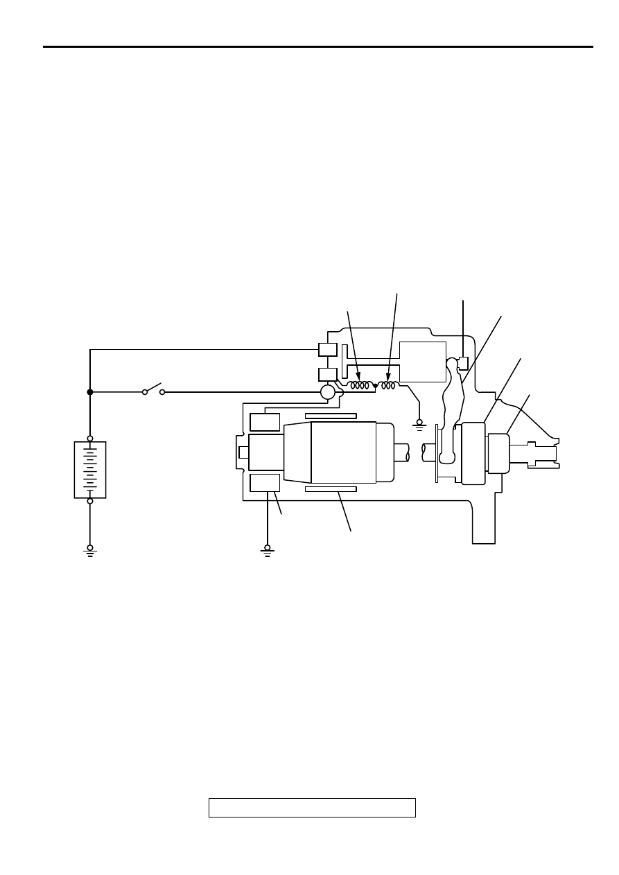
If the ignition switch is turned to the "START"
position, current flows in the coil provided inside
magnetic switch, attracting the plunger. When the
plunger is attracted, the lever connected to the
plunger is actuated to engage the starter clutch.
On the other hand, attracting the plunger will turn on
the magnetic switch, allowing the B terminal and M
terminal to conduct. Thus, current flows to engage
the starter motor.
When the ignition switch is returned to the "ON"
position after starting the engine, the starter clutch is
disengaged from the ring gear.
An overrunning clutch is provided between the pinion
and the armature shaft, to prevent damage to the
starter.
OPERATION
•
For models equipped with M/T, the clutch pedal
position switch contact is switched OFF when the
clutch pedal is depressed. When the ignition
switch is then switched to the "ST" position,
electricity flows to the starter relay and the starter
motor, the contact (magnetic switch) of the starter
is switched ON and the starter motor is activated.
NOTE: If the ignition switch is switched to the
"ST" position without the clutch pedal being
depressed, electricity flows to the starter relay
(coil), the clutch pedal position switch (contacts)
and to ground, with the result that the contacts of
the starter relay are switched OFF, and because
the power to the starter motor is thereby
interrupted, the starter motor in not activated.
B
M
S
AKX00196
PULL-IN COIL
HOLDING
COIL
PLUNGER
LEVER
PINION SHAFT
OVERRUNNING
CLUTCH
YOKE
BRUSH
ARMATURE
IGNITION
SWITCH
BATTERY
+
-
AB
STARTING SYSTEM
TSB Revision
ENGINE ELECTRICAL
16-22
•
For models equipped with A/T, when the ignition
switch is switched to the "ST" position while the
selector lever is at the "P" or "N" position, the
contact (magnetic switch) of the starter is
switched ON and the starter motor is activated.
DIAGNOSIS
M1162000700077
TROUBLESHOOTING HINTS
The starter motor does not operate at all.
•
Check the starter (coil).
•
Check for poor contact at the battery terminals and
starter.
•
Check the park/neutral position switch. <A/T>
•
Check starter relay. <M/T>
•
Check the clutch pedal position switch.
•
Check the theft-alarm starter relay.
The starter motor doesn't stop
•
Check the starter (magnetic switch).
TROUBLESHOOTING GUIDE
The starting system troubleshooting guide is shown in the
following chart.
STEP 1.
Q: Is the battery in good condition? (Refer to GROUP 54A,
Battery
−
On-vehicle Service - Battery Check
YES : Go to Step 2.
NO : Charge or replace the battery.
STEP 2.
•
Disconnect the starter motor S (solenoid) terminal
connector.
•
Using a jumper wire, apply battery positive voltage to the
starter motor S (solenoid) terminal.
•
Check the engine condition.
OK: Turns normally
Q: Does the starter motor operate normally?
YES :
•
Check the ignition switch (Refer to GROUP 54A,
Ignition Switch - Ignition Switch
.)
•
Check the starter relay.
•
Check the park/neutral position switch. (Refer to
GROUP 23A, On-vehicle Service - Essential
Service
.)
•
Check the line between the battery and starter
motor S (solenoid) terminal.
NO : Go to Step 3.
STARTING SYSTEM
TSB Revision
ENGINE ELECTRICAL
16-23
STEP 3.
•
Check the cable between starter B (battery) terminal and
battery positive terminal for connection and continuity.
Q: Is the starter cable in good condition?
YES : Go to Step 4.
NO : Repair or replace the cable.
STEP 4.
•
Check the connection and the continuity of the cable
between the starter motor body and the negative battery
terminal.
Q: Is the ground line in good condition?
YES : Go to Step 5.
NO : Repair or replace the cable.
STEP 5.
Q: Is the starter motor in good condition? (Refer to
Starting system
−
Starter motor - Inspection
.)
YES : Excessive rotational resistance of the engine.
NO : Replace the starter motor.
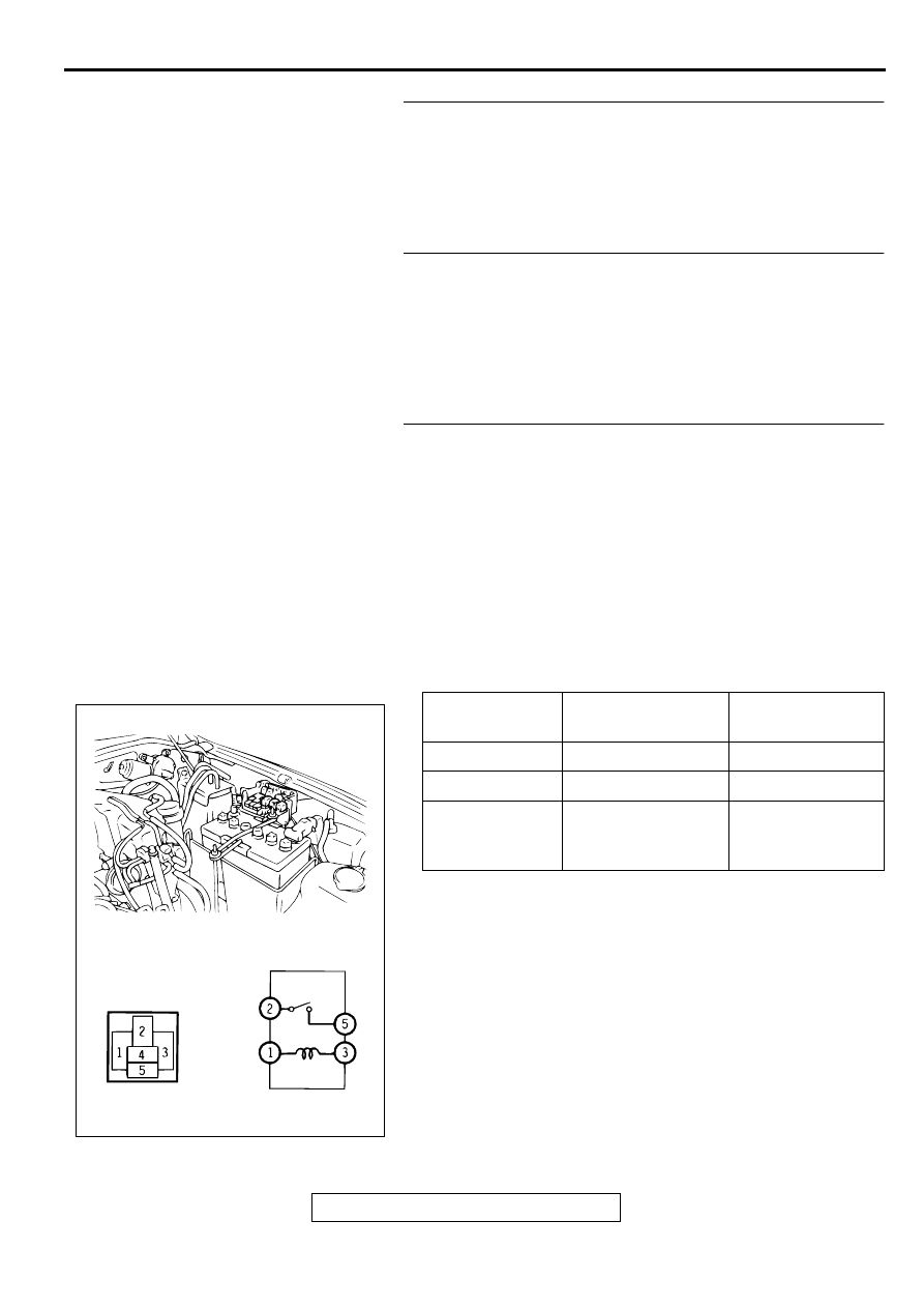
ON-VEHICLE SERVICE
STARTER RELAY CHECK
TESTER
CONNECTION
BATTERY
VOLTAGE
SPECIFIED
CONDITION
1 - 3
Not applied
Approximately 2
Ω
2 - 4
Not applied
Open circuit
Applied (Connect "+"
to the terminal 3 and
"-" to the terminal 1.)
Less than 2
Ω
AC005145
STARTING SYSTEM
TSB Revision
ENGINE ELECTRICAL
16-24
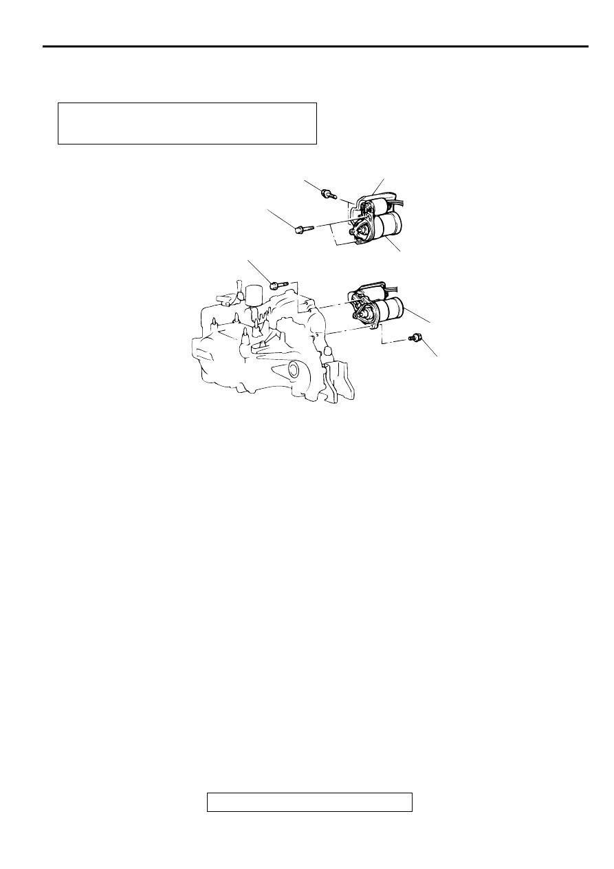
STARTER MOTOR ASSEMBLY
REMOVAL AND INSTALLATION
M1162001000082
Pre-removal and Post-installation Operation
•
Air Cleaner Removal and Installation (Refer to GROUP
15, Air Cleaner
AC000287
1
2
2
4.9 ± 1.0 N·m
44 ± 8 in-lb
30 ± 3 N·m
23 ± 2 ft-lb
30 ± 3 N·m
23 ± 2 ft-lb
30 ± 3 N·m
23 ± 2 ft-lb
AB
<2.4L ENGINE>
<3.0L ENGINE>
REMOVAL STEPS
1.
STARTER COVER <2.4L
ENGINE>
2.
STARTER MOTOR
Нет комментариевНе стесняйтесь поделиться с нами вашим ценным мнением.
Текст