Mitsubishi Eclipse / Eclipse Spyder (2000-2002). Service and repair manual — part 579
ANTI-SKID BRAKING SYSTEM (ABS) DIAGNOSIS
TSB Revision
ANTI-LOCK BRAKING SYSTEM (ABS)
35B-7
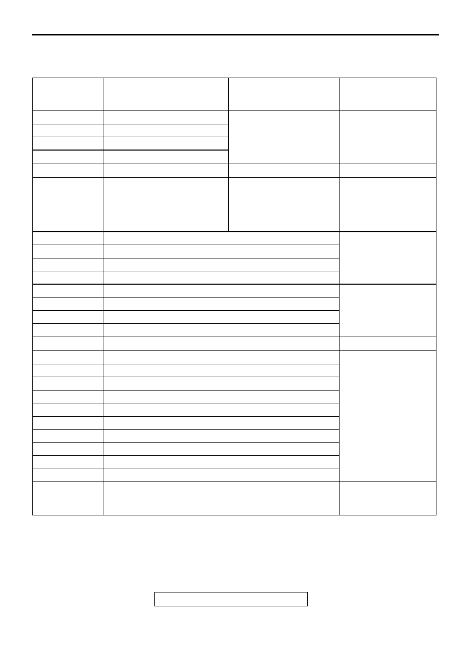
DIAGNOSTIC TROUBLE CODE CHART
M1352011300098
Follow the inspection chart that is appropriate for the
diagnostic trouble code.
NOTE:
.
*: Vehicles with TCL
DIAGNOSTIC
TROUBLE
CODE NO.
INSPECTION ITEM
DIAGNOSTIC CONTENT
REFERENCE PAGE
11
Front right wheel speed sensor
Open circuit or short circuit
12
Front left wheel speed sensor
13
Rear right wheel speed sensor
14
Rear left wheel speed sensor
15
Wheel speed sensor
Abnormal output signal
16
Power supply system
ABS-ECU power supply
voltage below or above the
standard value. Not
displayed if the voltage
recovers.
Check the battery.
(Refer to GROUP 54A,
Battery
−
On-vehicle
Service
−
Battery Check
.)
21
Front right wheel speed sensor
22
Front left wheel speed sensor
23
Rear right wheel speed sensor
24
Rear left wheel speed sensor
31*
TCL front left solenoid valve (IN)Refer to GROUP 35C,
Diagnostic Trouble Code
Chart
.)
32*
TCL front left solenoid valve (OUT)
33*
TCL front right solenoid valve (IN)
34*
TCL front right solenoid valve (OUT)
38
Stoplight switch system
41
ABS front right solenoid valve (IN)
42
ABS front left solenoid valve (IN)
43
ABS rear right solenoid valve (IN)
44
ABS rear left solenoid valve (IN)
45
ABS front right solenoid valve (OUT)
46
ABS front left solenoid valve (OUT)
47
ABS rear right solenoid valve (OUT)
48
ABS rear left solenoid valve (OUT)
51
Valve power supply
53
Pump motor
63
ABS-ECU
Replace the hydraulic
unit (Integrated with
ABS-ECU).
ANTI-SKID BRAKING SYSTEM (ABS) DIAGNOSIS
TSB Revision
ANTI-LOCK BRAKING SYSTEM (ABS)
35B-8
DIAGNOSTIC TROUBLE CODE PROCEDURES
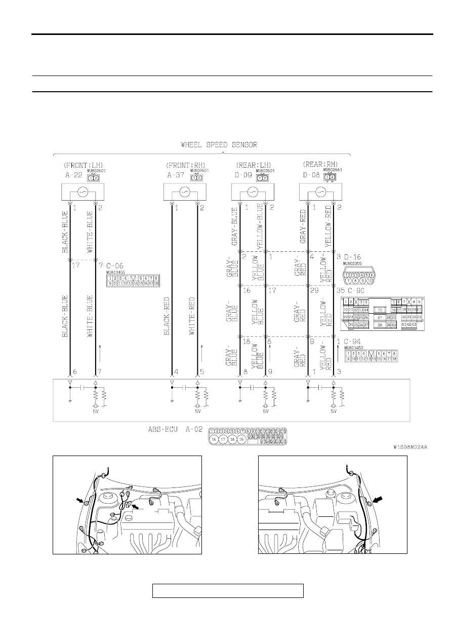
DTC 11, 12, 13, 14, 21, 22, 23, 24: Wheel Speed Sensor
Wheel Speed Sensor Circuit
AC001985
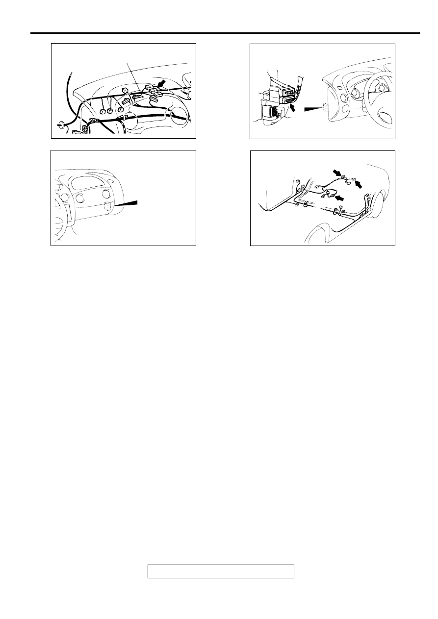
CONNECTORS: A-02, A-37
AC
A-02
A-37
AC002137AB
CONNECTOR: A-22
ANTI-SKID BRAKING SYSTEM (ABS) DIAGNOSIS
TSB Revision
ANTI-LOCK BRAKING SYSTEM (ABS)
35B-9
CIRCUIT OPERATION
•
A toothed ABS rotor generates a voltage pulse as
it moves across the pickup field of each wheel
speed sensor.
•
The amount of voltage generated at each wheel
is determined by the clearance between the ABS
rotor teeth and the wheel speed sensor, and by
the speed of rotation.
•
The wheel speed sensors transmit the frequency
of the voltage pulses and the amount of voltage
generated by each pulse to the ABS electronic
control unit (ABS-ECU).
•
The ABS hydraulic unit modulates the amount of
braking force individually applied to each wheel
cylinder.
ABS DTC SET CONDITIONS
•
DTCs 11, 12, 13, 14 are output when signal is not
input due to breakage of the wires of one or more
of the four wheel-speed sensors. DTCs 21, 22,
23, 24 are output in the following cases:
•
Open circuit is not found but no input is received
by one or more of the four wheel speed sensors
at 10 km/h (6 mph) or more.
•
Sensor output drops due to a malfunctioning
sensor or warped ABS rotor.
TROUBLESHOOTING HINTS (The most likely
causes for these DTCs are to set are:)
DTC 11, 12, 13, 14
•
Malfunction of the wheel speed sensor
•
Damaged wiring harness or connector
•
Malfunction of the hydraulic unit (integrated with
ABS-ECU)
DTC 21, 22, 23, 24
•
Malfunction of the wheel speed sensor
•
Damaged wiring harness or connector
•
Malfunction of the hydraulic unit (integrated with
ABS-ECU)
•
Malfunction of the ABS rotor
•
Malfunction of the wheel bearing
•
Excessive clearance between the sensor and
ABS rotor
DIAGNOSIS
Required Special Tools:
•
MB991223: Harness Set
•
MB991502: Scan Tool (MUT-II)
•
MB991529: Diagnostic Trouble Code Check Harness
AC004430 AB
CONNECTOR: C-06
COMBINATION METER
AC004408AB
CONNECTOR: C-90
AC004410AB
CONNECTOR: C-94
AC004426AB
CONNECTORS: D-08, D-09, D-16
D-09
D-16
D-08
ANTI-SKID BRAKING SYSTEM (ABS) DIAGNOSIS
TSB Revision
ANTI-LOCK BRAKING SYSTEM (ABS)
35B-10
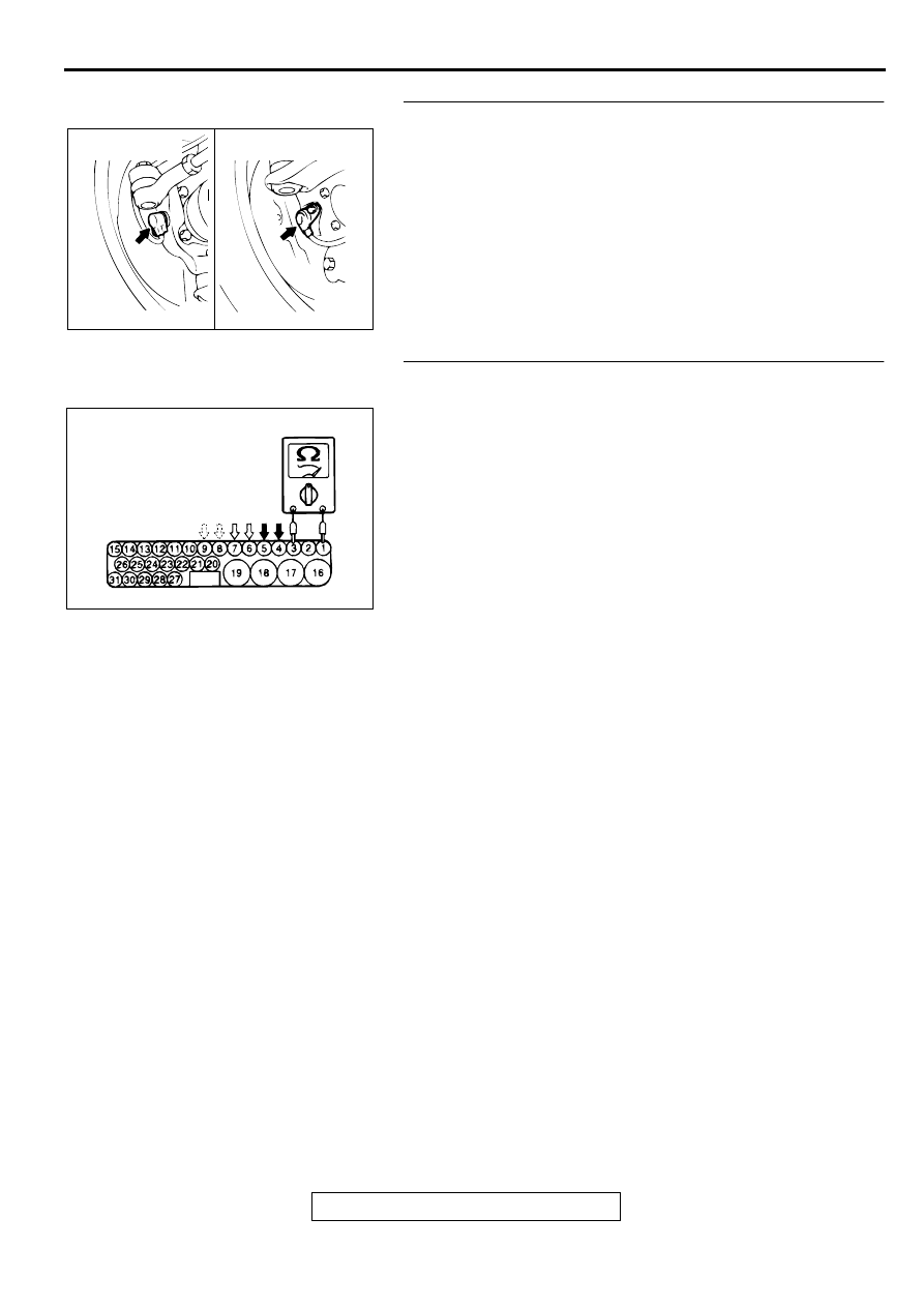
STEP 1. Check the wheel speed sensor installation.
Q: Is the wheel speed sensor bolted securely in place at
the front knuckle or the rear knuckle?
YES : Go to Step 2.
NO : Install it properly (Refer to
.) and go to Step
STEP 2. Check wheel speed sensor circuit at the ABS-ECU
connector A-02.
(1)Disconnect the connector A-02 and measure at the harness
side.
(2)Measure the resistance between the ABS-ECU connector
terminals 1 and 3, 4 and 5, 6 and 7, or 8 and 9.
Standard Value: 1.28
−
1.92 k
Ω
Q: Is the resistance between terminals 1 and 3, 4 and 5, 6
and 7, or 8 and 9 within the standard value?
YES : Go to Step 6.
NO <terminals 6 and 7> : Go to Step 3.
NO <terminals 4 and 5> : Go to Step 4.
NO <terminals 1 and 3, 8 and 9> : Go to Step 5.
AC000939
FRONT WHEEL
SPEED SENSOR
REAR WHEEL
SPEED SENSOR
AB
AC000940 AB
A-02 (HARNESS SIDE)
Нет комментариевНе стесняйтесь поделиться с нами вашим ценным мнением.
Текст