Mitsubishi Eclipse / Eclipse Spyder (2000-2002). Service and repair manual — part 580
ANTI-SKID BRAKING SYSTEM (ABS) DIAGNOSIS
TSB Revision
ANTI-LOCK BRAKING SYSTEM (ABS)
35B-11
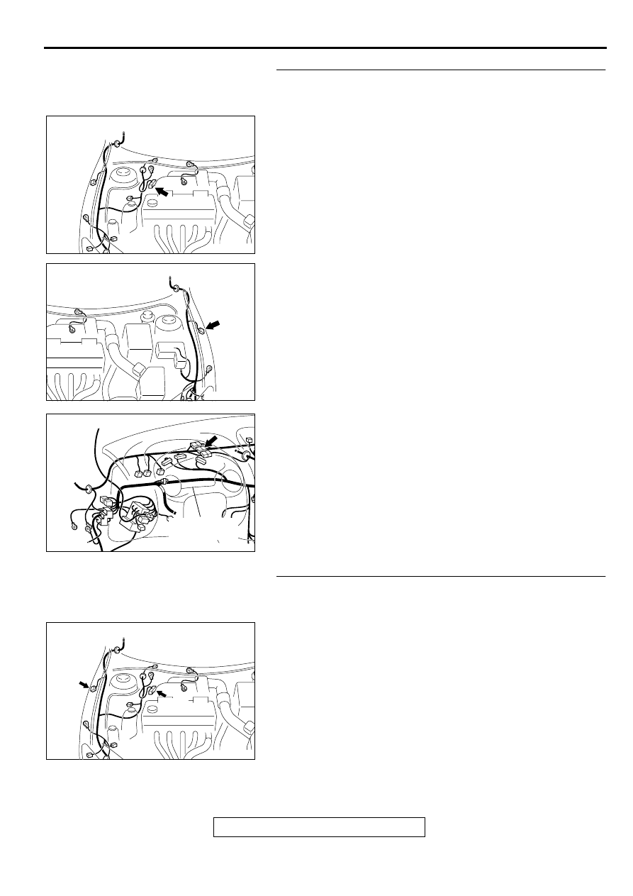
STEP 3. Check the harness wires between the ABS-ECU
connector A-02 and the wheel speed sensor <front: LH>
connector A-22.
NOTE: After inspecting the intermediate connector C-06,
inspect the wires. If the intermediate connector C-06 is
damaged, repair or replace it. Refer to GROUP 00E, Harness
Connector Inspection
. If the connector has been
repaired or replaced, go to Step 9.
Q: Is any of the harness wires between the ABS-ECU
connector A-02 and the wheel speed sensor <front: LH>
connector A-22 damaged?
YES : Repair it and go to Step 9.
NO : Go to Step 7.
STEP 4. Check the harness wires between the ABS-ECU
connector A-02 and the wheel speed sensor <front: RH>
connector A-37.
Q: Is any of the harness wires between the ABS-ECU
connector A-02 and the wheel speed sensor <front: RH>
connector A-37 damaged?
YES : Repair it and then go to Step 9.
NO : Go to Step 7.
AC001985
CONNECTOR: A-02
AD
AC002137AB
CONNECTOR: A-22
AC001989 BH
CONNECTOR: C-06
COMBINATION
METER
AC001985
CONNECTORS: A-02, A-37
AC
A-02
A-37
ANTI-SKID BRAKING SYSTEM (ABS) DIAGNOSIS
TSB Revision
ANTI-LOCK BRAKING SYSTEM (ABS)
35B-12
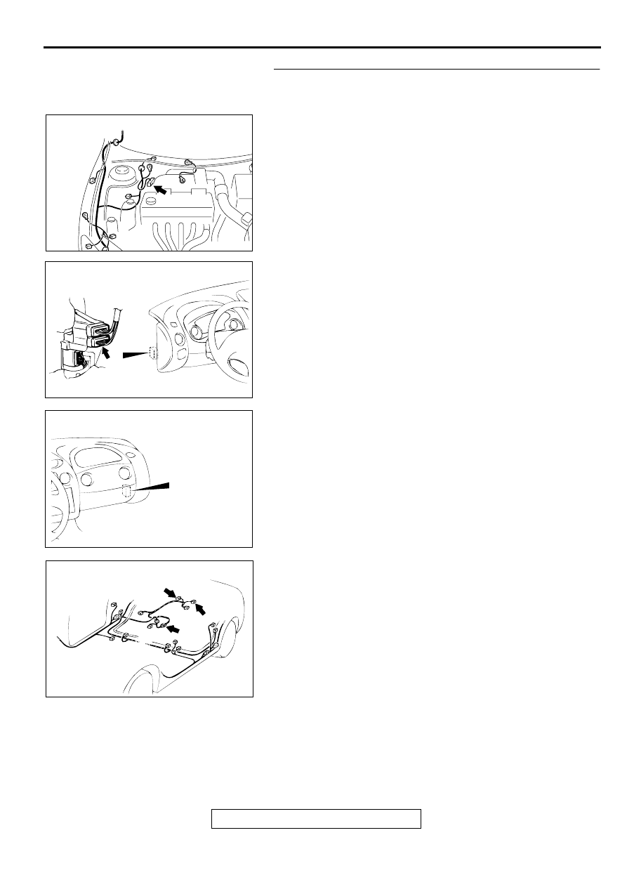
STEP 5. Check the harness wires between the ABS-ECU
connector A-02 and the wheel speed sensor connectors D-
08 <rear: RH> or D-09 <rear: LH>.
NOTE: After inspecting the intermediate connector C-90, C-94
or D-16, inspect the wires. If the intermediate connector C-90,
C-94 or D-16 is damaged, repair or replace it. Refer to GROUP
00E, Harness Connector Inspection
. If the connector
has been repaired or replaced, go to Step 9 .
Q: Is any of the harness wires between the ABS-ECU
connector A-02 and the wheel speed sensor connectors
D-08 <rear: RH> or D-09 <rear: LH> damaged?
YES : Repair it and then go to Step 9.
NO : Go to Step 7.
AC001985
CONNECTOR: A-02
AD
AC004408AB
CONNECTOR: C-90
AC004410AB
CONNECTOR: C-94
AC004426AB
CONNECTORS: D-08, D-09, D-16
D-09
D-16
D-08
ANTI-SKID BRAKING SYSTEM (ABS) DIAGNOSIS
TSB Revision
ANTI-LOCK BRAKING SYSTEM (ABS)
35B-13
STEP 6. Check the wheel speed sensor output voltage.
Refer to
.
Output Voltage:
•
When measured with a voltmeter: 42 mV or more
•
When measured with oscilloscope (maximum voltage): 200
mV or more
Q: Does the voltage meet the specification?
YES : Replace the hydraulic unit (integrated with ABS-ECU)
and then go to Step 9.
NO : Go to Step 7.
STEP 7. Check the wheel speed sensor or ABS rotor.
Refer to
. If there is a damage in any of the following
check items, replace the wheel speed sensor or the ABS rotor.
Check items:
•
Wheel speed sensor internal resistance
Standard value: 1.28
−
1.92 k
Ω
•
Insulation between the wheel speed sensor body and
connector terminals
•
Toothed ABS rotor
Q: Is the wheel speed sensor or ABS rotor damaged?
YES : Replace the faulty part and then go to Step 9.
NO : Go to Step 8.
STEP 8. Check the wheel bearing.
Refer to GROUP 26, Front Hub Assembly
, or GROUP
27, Rear Axle Hub
Q: Is the wheel bearing damaged?
YES : Replace it and then go to Step 9.
NO : Go to Step 9.
STEP 9. Check the diagnostic trouble codes.
Q: Do the diagnostic trouble codes 11, 12, 13, 14, 21, 22, 23
or 24 reset?
YES : Go to Step 1.
NO : This diagnosis is complete.
ANTI-SKID BRAKING SYSTEM (ABS) DIAGNOSIS
TSB Revision
ANTI-LOCK BRAKING SYSTEM (ABS)
35B-14
DTC 15: Wheel Speed Sensor (Abnormal Output Signal)
WHEEL SPEED SENSOR CIRCUIT
Refer to
.
CIRCUIT OPERATION
Refer to
.
ABS DTC SET CONDITIONS
•
DTC 15 is output when output signal produced by
any of wheel speed sensor is abnormal
(excluding short and open-circuits).
TROUBLESHOOTING HINTS (The most likely
causes for this DTC is to set are:)
•
Improper installation of the wheel speed sensor
•
Malfunction of the wheel speed sensor
•
Damaged wiring harness or connector
•
Malfunction of the ABS rotor
•
Malfunction of the wheel bearing
DIAGNOSIS
Required Special Tools:
•
MB991223: Harness Set
•
MB991502: Scan Tool (MUT-II)
•
MB991529: Diagnostic Trouble Code Check Harness
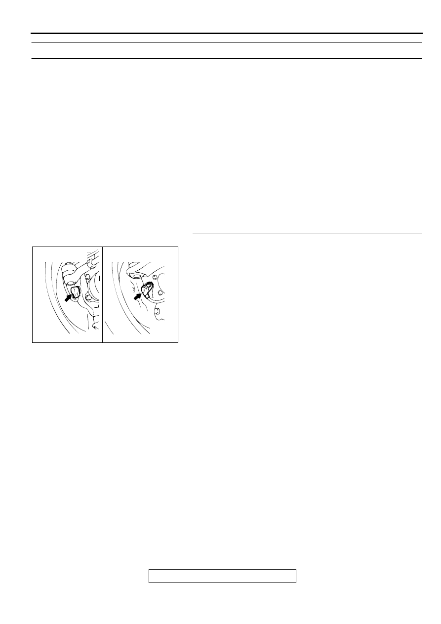
STEP 1. Check the wheel speed sensor installation.
Q: Are the wheel speed sensors bolted securely in place at
the front knuckle or the rear knuckle?
YES : Go to Step 2.
NO : Install it properly (Refer to
.). Then go to
Step 8.
AC000939
FRONT WHEEL
SPEED SENSOR
REAR WHEEL
SPEED SENSOR
AB
Нет комментариевНе стесняйтесь поделиться с нами вашим ценным мнением.
Текст