Mitsubishi Eclipse / Eclipse Spyder (2000-2002). Service and repair manual — part 116
MULTIPORT FUEL INJECTION (MFI) DIAGNOSIS
TSB Revision
MULTIPORT FUEL INJECTION (MFI) <2.4L ENGINE>
13A-163
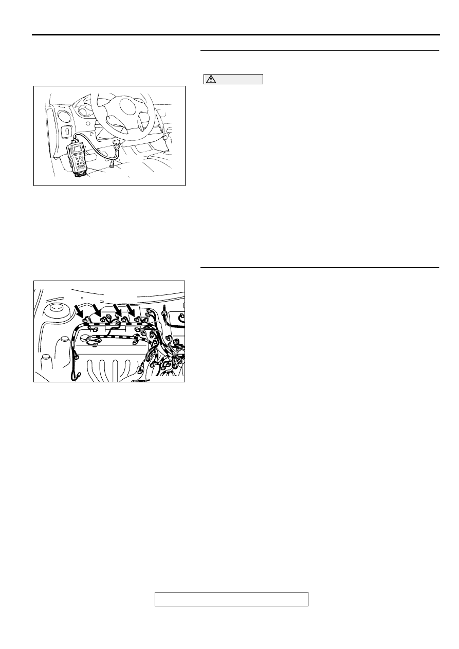
STEP 1. Using scan tool MB991502, check actuator test
item 01, 02, 03, 04: Injectors.
CAUTION
To prevent damage to scan tool MB991502, always turn the
ignition switch to the "LOCK" (OFF) position before
connecting or disconnecting scan tool MB991502.
(1) Connect scan tool MB991502 to the data link connector.
(2) Start the engine and run at idle.
(3) Set scan tool MB991502 to the actuator testing mode for
item 01, 02, 03, 04 Injectors.
(4) Warm up the engine to normal operating temperature: 80
°
C to 96
°
C(176
°
F to 205
°
F).
•
Does the idle state worsen when the injector is cut off.
(Does idling become unstable or does the engine stall)
(5) Turn the ignition switch to the "LOCK" (OFF) position.
Q: Is the actuator operating properly?
YES : It can be assumed that this malfunction is intermittent.
Refer to GROUP 00, How to Use Troubleshooting/
Inspection Service Points (
NO : Go to Step 2.
STEP 2. Check the connector at injector for damage.
a. Check the connector B-01 when checking No.1 cylinder.
b. Check the connector B-02 when checking No.2 cylinder.
c. Check the connector B-05 when checking No.3 cylinder.
d. Check the connector B-06 when checking No.4 cylinder.
Q: Is the connector in good condition?
YES : Go to Step 3.
NO : Repair or replace it. Refer to GROUP 00E, Harness
Connector Inspection (
). Then go to Step 10.
AKX01177
16 PIN
MB991502
AB
AK000273AB
AK000273
CONNECTOR : B-01, B-02, B-05, B-06
B-01 B-02 B-05 B-06
MULTIPORT FUEL INJECTION (MFI) DIAGNOSIS
TSB Revision
MULTIPORT FUEL INJECTION (MFI) <2.4L ENGINE>
13A-164
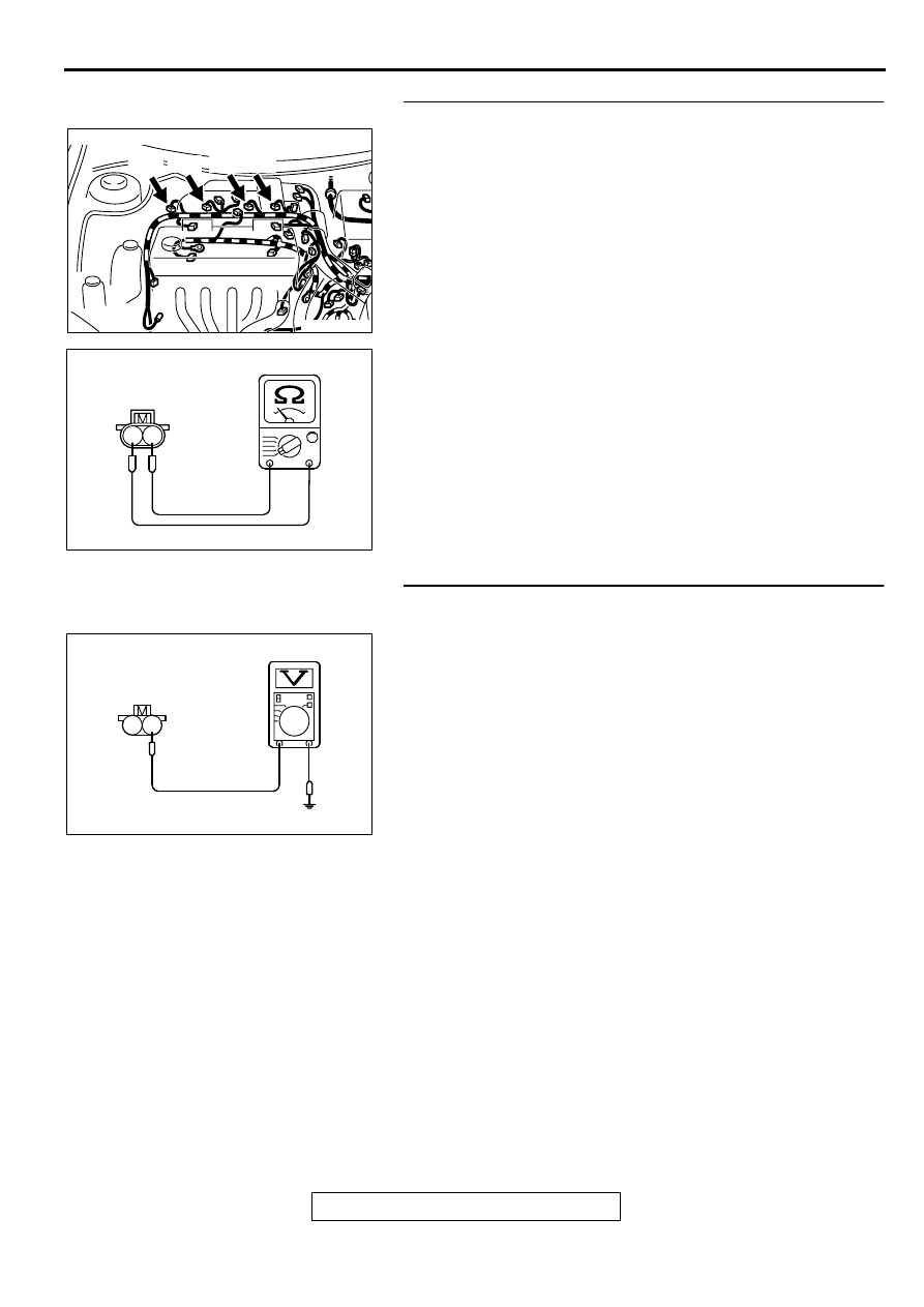
STEP 3. Check the injector.
(1) Disconnect the injector connector B-01 <No.1 cylinder> or
B-02 <No.2 cylinder> or B-05 <No.3 cylinder> or B-06
<No.4 cylinder>.
(2) Measure the resistance between injector side connector
terminal 1 and 2.
Standard value: 13
−
16 ohm [at 20
°
C (68
°
F)]
Q: Is the resistance standard value?
YES : Go to Step 4.
NO : Replace the injector. Then go to Step 10.
STEP 4. Check the power supply voltage at injector
connector.
(1) Disconnect connector B-01 <No.1 cylinder> or B-02 <No.2
cylinder> or B-05 <No.3 cylinder> or B-06 <No.4 cylinder>
and measure at the harness side.
(2) Turn the ignition switch to the "ON" position.
(3) Measure the voltage between terminal 1 and ground.
•
Voltage should be battery positive voltage.
(4) Turn the ignition switch to the "LOCK" (OFF) position.
Q: Is the voltage normal?
YES : Go to Step 6.
NO : Go to Step 5.
AK000273AB
AK000273
CONNECTOR : B-01, B-02, B-05, B-06
B-01 B-02 B-05 B-06
AK000559
2
1
INJECTOR SIDE
CONNECTOR
AB
AK000560
1
2
B-01,B-02,B-05,B-06
HARNESS SIDE
CONNECTOR
AD
MULTIPORT FUEL INJECTION (MFI) DIAGNOSIS
TSB Revision
MULTIPORT FUEL INJECTION (MFI) <2.4L ENGINE>
13A-165
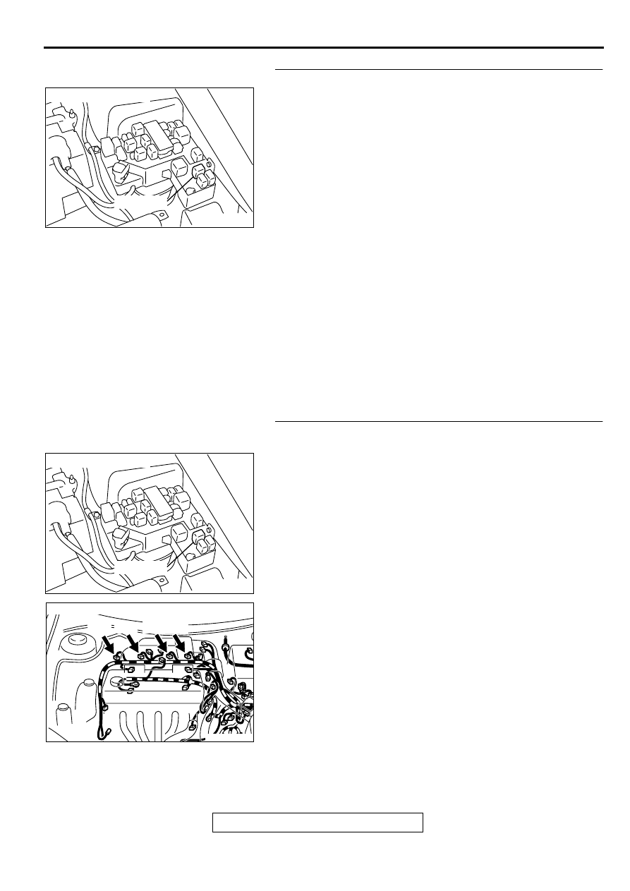
STEP 5. Check connector A-21X at MFI relay for damage.
Q: Is the connector in good condition?
YES : Repair harness wire between MFI relay connector
and injector connector because of open circuit or
short circuit to ground.
a. Repair harness wire between MFI relay
connector A-21X terminal 1 and injector
connector B-01 terminal 1 when checking No.1
cylinder.
b. Repair harness wire between MFI relay
connector A-21X terminal 1 and injector
connector B-02 terminal 1 when checking No.2
cylinder.
c. Repair harness wire between MFI relay
connector A-21X terminal 1 and injector
connector B-05 terminal 1 when checking No.3
cylinder.
d. Repair harness wire between MFI relay
connector A-21X terminal 1 and injector
connector B-06 terminal 1 when checking No.4
cylinder.
Then go to Step 10.
NO : Repair or replace it. Refer to GROUP 00E, Harness
Connector Inspection (
). Then go to Step 10.
STEP 6. Check for harness damage between MFI relay
connector and injector connector.
a. Check the harness wire between MFI relay connector A-
21X terminal 1 and injector connector B-01 terminal 1 when
checking No.1 cylinder.
b. Check the harness wire between MFI relay connector A-
21X terminal 1 and injector connector B-02 terminal 1 when
checking No.2 cylinder.
c. Check the harness wire between MFI relay connector A-
21X terminal 1 and injector connector B-05 terminal 1 when
checking No.3 cylinder.
d. Check the harness wire between MFI relay connector A-
21X terminal 1 and injector connector B-06 terminal 1 when
checking No.4 cylinder.
Q: Is the harness wire in good condition?
YES : Go to Step 7.
NO : Repair it. Then go to Step 10.
AK000226
AK000226AB
CONNECTOR : A-21X
MFI RELAY
AK000226
AK000226AB
CONNECTOR : A-21X
MFI RELAY
AK000273AB
AK000273
CONNECTOR : B-01, B-02, B-05, B-06
B-01 B-02 B-05 B-06
MULTIPORT FUEL INJECTION (MFI) DIAGNOSIS
TSB Revision
MULTIPORT FUEL INJECTION (MFI) <2.4L ENGINE>
13A-166
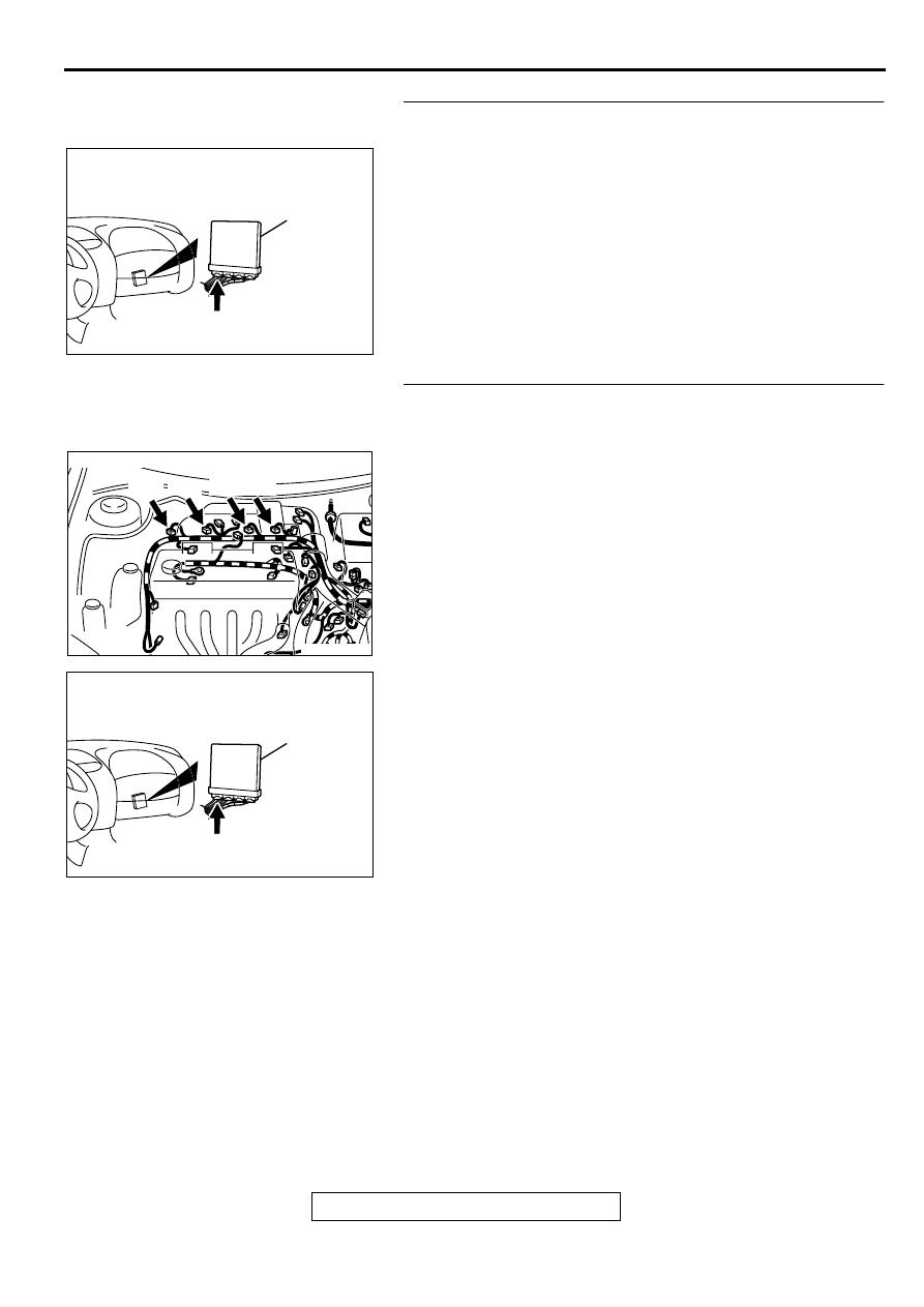
STEP 7. Check connector C-49 at ECM <M/T> or connector
C-50 at PCM <A/T> for damage.
Q: Is the connector in good condition?
YES : Go to Step 8.
NO : Repair or replace it. Refer to GROUP 00E, Harness
Connector Inspection (
). Then go to Step 10.
STEP 8. Check for open circuit and short circuit to ground
and harness damage between injector connector and ECM
connector <M/T> or PCM connector <A/T>.
a. Check the harness wire between injector connector B-01
terminal 2 and ECM connector C-49 terminal 1 <M/T> or
PCM connector C-50 terminal 1 <A/T> when checking No.1
cylinder.
b. Check the harness wire between injector connector B-02
terminal 2 and ECM connector C-49 terminal 14 <M/T> or
PCM connector C-50 terminal 9 <A/T> when checking No.2
cylinder.
c. Check the harness wire between injector connector B-05
terminal 2 and ECM connector C-49 terminal 2 <M/T> or
PCM connector C-50 terminal 24 <A/T> when checking
No.3 cylinder.
d. Check the harness wire between injector connector B-06
terminal 2 and ECM connector C-49 terminal 15 <M/T> or
PCM connector C-50 terminal 2 <A/T> when checking No.4
cylinder.
Q: Is the harness wire in good condition?
YES : Go to Step 9.
NO : Repair it. Then go to Step 10.
AK000280
C-49,C-50
ECM<M/T>
OR
PCM<A/T>
CONNECTORS:C-49<M/T>,C-50<A/T>
BC
AK000273AB
AK000273
CONNECTOR : B-01, B-02, B-05, B-06
B-01 B-02 B-05 B-06
AK000280
C-49,C-50
ECM<M/T>
OR
PCM<A/T>
CONNECTORS:C-49<M/T>,C-50<A/T>
BC
Нет комментариевНе стесняйтесь поделиться с нами вашим ценным мнением.
Текст